Checking the Inputs and Outputs ESIE11-02
3–20 Part 3 – Troubleshooting
3
1
3
4
5
3.7 Electrical Error Overview: EUWA*5-24KBZW1 and EUWY*5-24KBZW1
Introduction This map gives an overview of the most common electrical errors that can occur on the
EUWA*5-24KBZW1 and the EUWY*5-24KBZW1.
See also "Wiring Diagram: EUWA*5-24KBZW1 and EUWY*5-24KBZW1" on page 1–75.
General items Before proceeding, confirm the status of the following items:
■ Microchiller compact: is the controller initialized? Are all parameters set?
■ I/O PCB: Is the PCB working?
If the HAP (green led) blinks, the PCB is working.
General remark
about H1P and H2P
on I/O PCB
If an electrical error is solved, H1P (red) and H2P (red) on the I/O PCB keep their latest status. H1P
and H2P can only be reset by switching the I/O PCB OFF/ON.
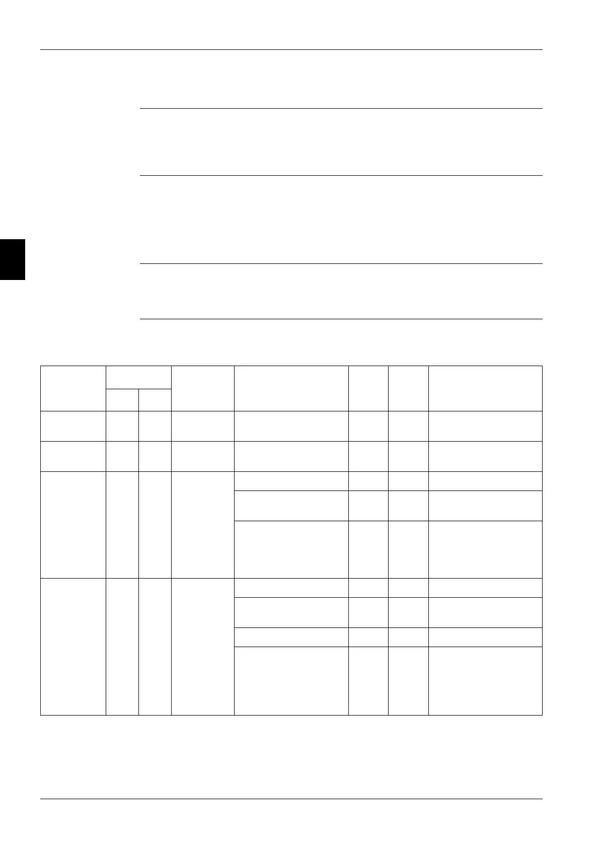
Error list
microchiller
compact controller
The table below contains an error list for the microchiller compact controller.
Microchiller
compact
controller
I/O PCB General
error
description
Possible cause Part
Con-
nector
Action
H1P H2P
e1 OFF OFF Sensor input
1 broken
Evaporator inlet water
sensor broken
R3T X60A Check sensor.
e2 OFF OFF Sensor input
2 broken
Evaporator outlet water
sensor broken
R4T X61A Check sensor.
e3 Or fl and
hp1
OFF ON Fuse blown F4 X1A Check fuse.
Reverse phase error X1A Check L1/L2/L3
connection.
I/O PCB broken A2P
■ Check I/O PCB (HAP
must be blinking).
■ Check trafo power
supply.
fl OFF OFF Flow error Flow switch open S10L X65A Green LED’s = flow
Overcurrent protection
pump
K6A X28A Reset overcurrent.
Shortcut X28A Check shortcut
Wireharness between I/O
PCB and microchiller
compact
X71A
X1
■ Check connections on
X71A (I/O PCB)
■ Check connections on
X1 (microchiller
compact)
 Loading...