Checking the Inputs and Outputs ESIE11-02
3–18 Part 3 – Troubleshooting
3
1
3
4
5
3.6 Checking the Power Supply and Fuses: EUWA*5-24KBZW1 and
EUWY*5-24KBZW1
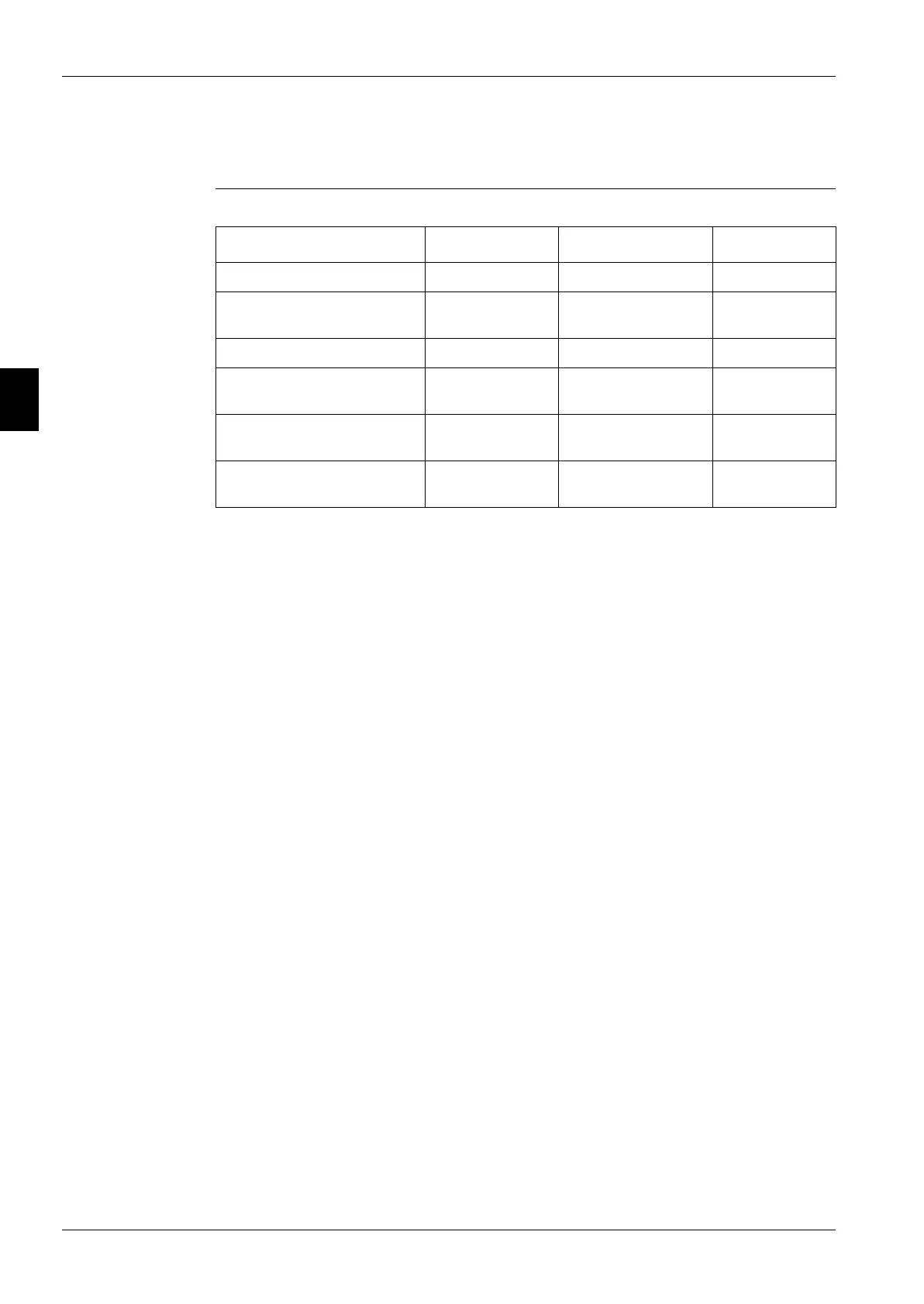
Overview The table below contains an overview of the circuits, the voltage and their fuse codes.
Circuit Wiring code Type / voltage Fuse code
Main supply L1 + L2 + L3 + N 3 phases / 400 V AC F1+F2+F3
Control circuit I/O PCB L1 + N
L3 + N
1 phase / 230 V AC
1 phase / 230 V AC
F4
F1U
Control circuit controller TR1-sec. 24 V AC F3U, F5U
Control circuit (pump) for
EUWAN5-24KBZW1
X1M 8-7 24 V AC F6
Fan circuit for
EUWA*5-12KBZW1
L1 + N 1 phase / 230 V AC F7
Fan circuit for
EUWA*18-24KBZW1
L1 + N 1 phase / 230 V AC F8
 Loading...