Functional Description ESIE11-02
2–10 Part 2 – Functional Description
3
1
2
4
5
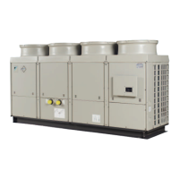
1.7 Thermostat Control: EUWA*5-24KBZW1 and EUWY*5-24KBZW1
Functional diagram
5-12HP
The illustration below shows the thermostat control of 5-12HP.
Functional diagram
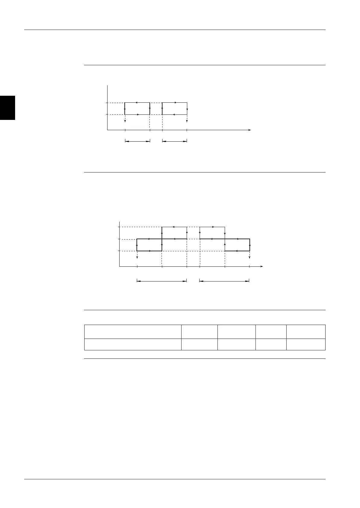
16-24HP
The illustration below shows the thermostat control of 16-24HP.
Controller The table below describes the step difference.
12°C
ON
OFF
Compressor
15°C Inlet water temperature
evap. (°C)
Step
difference
Step
difference
r01: Cooling set point
(default 12°C)
r03:
Heating set point
(default 30°C) only for
EUWY*5-24KBZW1
r21: Cooling set point 2
r22:
Heating set point 2
only for
EUWY*5-24KBZW1
27°C 30°C
r02
r04
r01/r21 r03/r22
12°C
ON
OFF
Compressor
15°C
Inlet water temperature
evap. (°C)
Step
difference
Step
difference
13.5°C 27°C 28.5°C 30°C
Compressor 2
ON
OFF
Compressor 1
r01/r21
r02 r04
r03/r22
r01: Cooling set point
(default 12°C)
r03:
Heating set point
(default 30°C) only for
EUWY*5-24KBZW1
r21: Cooling set point 2
r22:
Heating set point 2
only for
EUWY*5-24KBZW1
Description Lower limit Upper limit Step Default
r02 and/or r04: Step difference (°C) 0.3 19.9 0.1 3.0
 Loading...