 Loading...
Do you have a question about the Dell EMC PowerEdge MX740c and is the answer not in the manual?
| Product Type | Server |
|---|---|
| Management | iDRAC9 with Lifecycle Controller |
| Processor | Up to two Intel Xeon Scalable processors, up to 28 cores per processor |
| Memory | Up to 3TB DDR4 memory |
| Drive Bays | Up to 6 x 2.5" |
| Storage | SAS, SATA, NVMe SSD |
| RAID Support | HBA330 |
| Chassis | PowerEdge MX7000 |
| Expansion Slots | PCIe slots available in the MX7000 chassis |
| Networking | 2 x 25GbE ports via fabric A and B; Optional mezzanine card provides additional connectivity |
General safety warnings for handling system components.
Prerequisite steps before servicing internal components.
Prerequisite steps after servicing internal components.
Step-by-step guide to remove the sled from the enclosure.
Step-by-step guide to install the sled into the enclosure.
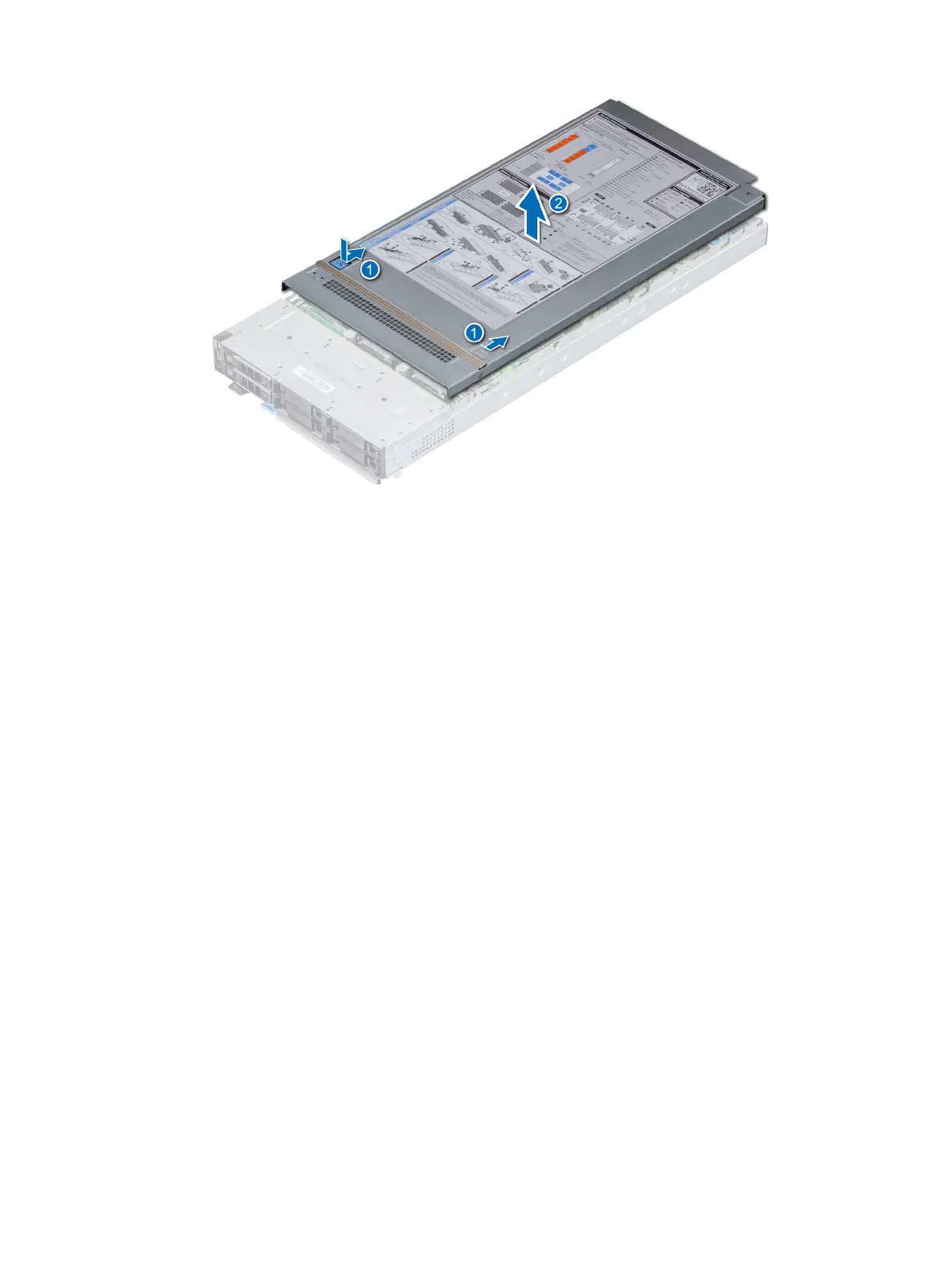
Steps to remove the system cover.
Steps to install the system cover.
Steps to remove the air shroud.
Steps to install the air shroud.
Steps to remove a drive carrier from a drive slot.
Steps to install a drive carrier into a drive slot.
Steps to remove a drive from its carrier.
Steps to install a drive into its carrier.
Steps to remove the drive backplane.
Steps to install the drive backplane.
Steps to remove the drive cage.
Steps to install the drive cage.
Steps to remove the battery backup unit.
Steps to install the battery backup unit.
Steps to remove the BBU from its cage.
Steps to install the BBU into its cage.
Steps to remove the control panel.
Steps to install the control panel.
Guidelines for optimal system memory performance and configuration.
Recommended guidelines for installing NVDIMM-N memory modules.
Steps to remove a memory module from its socket.
Steps to install a memory module into its socket.
Steps to remove the processor and heat sink module.
Steps to remove the processor from its heat sink module.
Steps to install the processor into its heat sink module.
Steps to install the processor and heat sink module onto the system board.
Steps to remove the iDRAC card.
Steps to install the iDRAC card onto the system board.
Steps to remove the PERC card.
Steps to install the PERC card onto the system board.
Steps to remove the Jumbo PERC card.
Steps to install the Jumbo PERC card.
Steps to remove the IDSDM card.
Steps to install the IDSDM card onto the system board.
Steps to remove a MicroSD card from the IDSDM card.
Steps to install a MicroSD card into the IDSDM card.
Steps to remove the M.2 BOSS module.
Steps to install the M.2 BOSS module onto the system board.
Steps to remove the M.2 BOSS card from the module.
Steps to install the M.2 BOSS card into the module.
Steps to remove the Mezzanine card.
Steps to install the Mezzanine card onto the system board.
Steps to remove the mini Mezzanine card.
Steps to install the mini Mezzanine card onto the system board.