860-00186-00 Rev J
Digital Ally Inc.| Device Configuration
Input Sensor Device Detection, Threshold, and Wiring Guide
To configure an input sensor, the signaling of the device must be known. To determine the signaling,
measure the voltage for the normal or inactive state of the device and the voltage for the triggered or
active state. Use the input sensor worksheet located in your installation guide to record measurements.
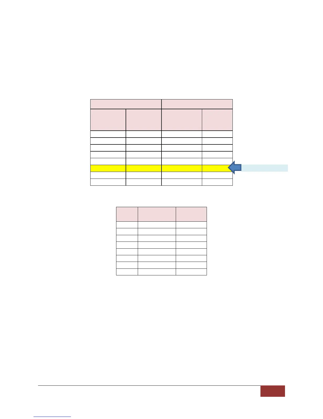
When configuring sensors, first determine the Trigger Operation; second, the direction for the Detection
Type; then select the Threshold setting nearest to the triggered state. The figure below illustrates these
steps:
Figure 3-17a: Detection and Threshold parameters for input sensors.
Signal from Trigger Device
Triggered or
Active State
Figure 3-17b: Interface box input cable wiring color code
How to Configure a Backup Camera
The DVM-800 can provide a backup camera image on the LCD when the vehicle is shifted into reverse
gear. In addition, the DVM-800 can be configured to record the backup event. An optional backup
camera or license plate camera kit is required.
The backup camera is connected to the DVM CAM2 input. The vehicle’s reverse gear signal must be
connected to Sensor Input #1 of the IF Box (consult the DVM-800 Installation Guide for more
information).
The example below illustrates a typical backup camera configuration. Using this example, your DVM-800
will display the backup camera image on the LCD whenever the reverse gear is active, but will not start a
recorded event. When recording the Backup Camera Event is not required, configure the Type for
Sensor #1 as “Sensor Only”. If recording the backup camera event is required, configure the Type for
Sensor #1 as “Event Trigger”. The LCD can be configured to be ON or OFF in either mode. Note that
 Loading...