Maintenance 8. Arm #4
132 G3 Rev.14
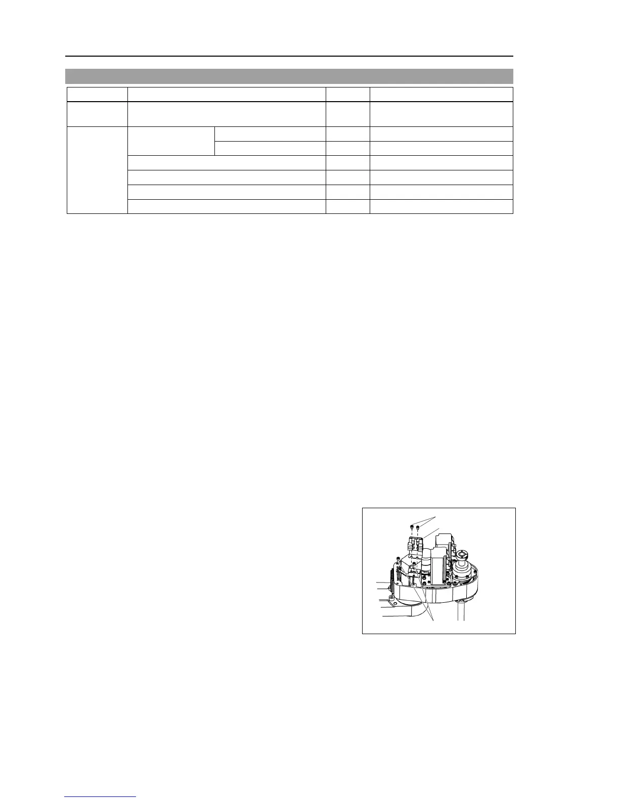
8.1 Replacing Joint #4 Motor
Maintenance
parts
AC Servo Motor (150 W) 1 R13B000615
Tools
Hexagonal wrench
Belt tension 74 N (7.5 ± 0.5 kgf)
Suitable cord (Length about 800 mm)
A brake is mounted on the Joints #3 motor to prevent the shaft from lowering due to the
weight of the end effector while the power to the Controller is OFF or while the motor is
in OFF status (MOTOR OFF).
Note that the brake will not work during the replacement procedure.
Move the shaft down to its lower limit before starting the replacement procedure by
following the removal steps from (1) to (3).
Push down the shaft to its lower limit while pressing the brake release switch. Be
sure to keep enough space and prevent the
hitting any peripheral
equipment.
The brake release switch affects only Joint #3. When the brake release switch is
pressed, the brake for Joint #3 is released simultaneously.
shaft while the brake release switch is being pressed because
the shaft
may be lowered by the weight of an end effector
top cover and the arm bottom cover.
For details, refer to Maintenance: 3. Covers.
Remove the battery board from Arm
Be careful of the connector not to fall off when
removing
If the connector falls off, the joints
Remove the user plate and ground wire secured on Arm #2.
Cut off a wire tie used for bundling the motor cables and signal cables.
Disconnect the following connectors.
X241, X41 (Hold the claw to remove.)
Connector X64 (for backup cable connector of Joint #4)
 Loading...


