
Do you have a question about the Epson G3 Series and is the answer not in the manual?
| Number of axes | 4 |
|---|---|
| Payload | 3 kg |
| Repeatability | ±0.01 mm |
| Degrees of Freedom | 4 |
| Type | SCARA |
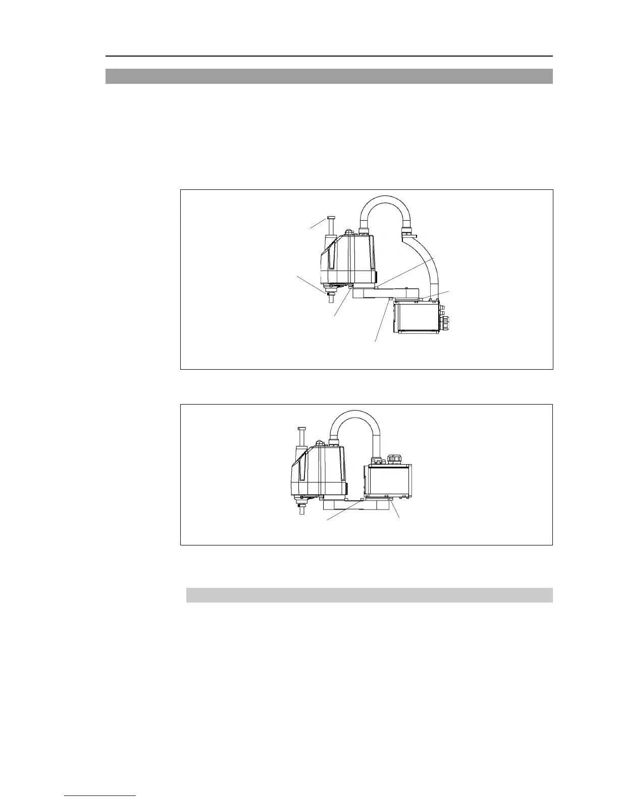
| Installation | Wall, Ceiling |
Important safety considerations indicated by symbols; read descriptions for safe operation.
Details on G3 series manipulator features, model differences, and technical specifications.
Guidelines for installing the robot system in suitable environments and related procedures.
Methods for setting motion range using pulse range for all joints.
Setting motion range by physically limiting absolute movement area with mechanical stops.
Setting upper and lower limits of X and Y coordinates using software, not affecting physical range.
Diagrams showing standard (maximum) motion range specifications and definitions of areas.
Procedures and safety precautions for performing routine maintenance on the robot system.
Description of maintenance inspections and procedures, emphasizing schedule adherence and safety.
Procedures for removing and installing covers during maintenance, with safety warnings.
Procedures for replacing cable units, wiring diagrams, power cables, and user cables.
Procedures for replacing the Joint #1 motor and reduction gear unit, including safety precautions.
Procedures for replacing the Joint #2 motor and reduction gear unit, with safety guidelines.
Procedures for replacing the Joint #3 motor, timing belt, and brake, with safety measures.
Procedures for replacing the Joint #4 motor and timing belt, with safety guidelines.
Detailed steps for replacing the Arm #1 unit, including software configuration changes.
Procedure for replacing bellows, with precautions regarding dust emission.
Procedures for greasing and replacing the ball screw spline unit, with safety warnings.
Information and procedures for handling and replacing the lithium battery and battery board.
Procedure for removing and installing the LED lamp.
About calibration, procedures using wizard and without wizard, and accuracy testing.
List of common and environment-specific parts for maintenance, including codes and references.


