EasyManuals Logo
Home>Epson>Robotics>G3 Series

Epson G3 Series User Manual

Epson G3 Series
200 pages
To Next Page IconTo Next Page
To Previous Page IconTo Previous Page
Page #118 background imageLoading...
Page #118 background image
Maintenance 5. Arm #1
106 G3 Rev.14
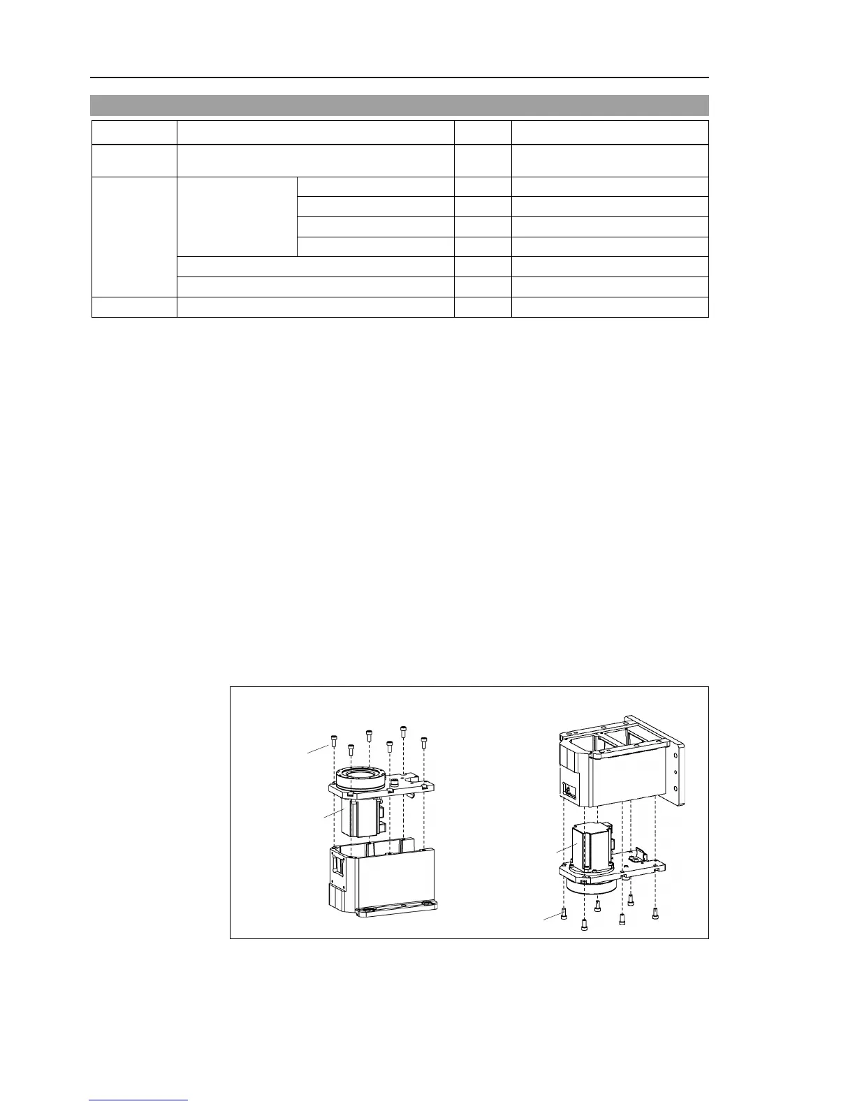
5.1 Replacing Joint #1 Motor
Name Quantity Note
Maintenance
parts
AC Servo Motor (200 W) 1 R13B000614
Tools
Hexagonal wrench
width across flats: 2 mm
1
For M4 set screw
width across flats: 3 mm
1
For M4 screw
width across flats: 4 mm
1
For M5 screw
width across flats: 5 mm
1
For M6 screw
Torque wrench
1
Wiping cloth
1
For wiping grease
Grease
Grease (SK-1A)
4 g
Joint #1 motor
Removal
(1)
Remove the connector
plate.
For details, refer to Maintenance: 3.4 Connector Plate.
(2)
Remove the connector sub plate.
For details, refer to Maintenance: 3.5 Connector Sub Plate.
(3)
Disconnect the following connectors.
Connectors X111, X10 (Hold the claw to remove.)
Connector XB10
(4)
Remove the
heatsink plate.
For details, refer to Maintenance: 3.7 Heatsink Plate.
(5)
R
emove the heat release sheet from the Motor.
(6)
Unscrew and remove the bolts from Joint #1 flange mounting on the base.
Mounting positions of the base and Joint #1 flange are determined by the positioning
pin.
Be sure to keep the positioning pin.
Table Top Mounting
Multiple Mounting
6-M6×15
Motor
6-M6×15
Motor

Table of Contents

Questions and Answers:

Question and Answer IconNeed help?

Do you have a question about the Epson G3 Series and is the answer not in the manual?

Epson G3 Series Specifications

General IconGeneral
BrandEpson
ModelG3 Series
CategoryRobotics
LanguageEnglish

Related product manuals