EasyManuals Logo
Home>Epson>Robotics>G3 Series

Epson G3 Series User Manual

Epson G3 Series
200 pages
To Next Page IconTo Next Page
To Previous Page IconTo Previous Page
Page #74 background imageLoading...
Page #74 background image
Setup & Operation 5. Motion Range
62 G3 Rev.14
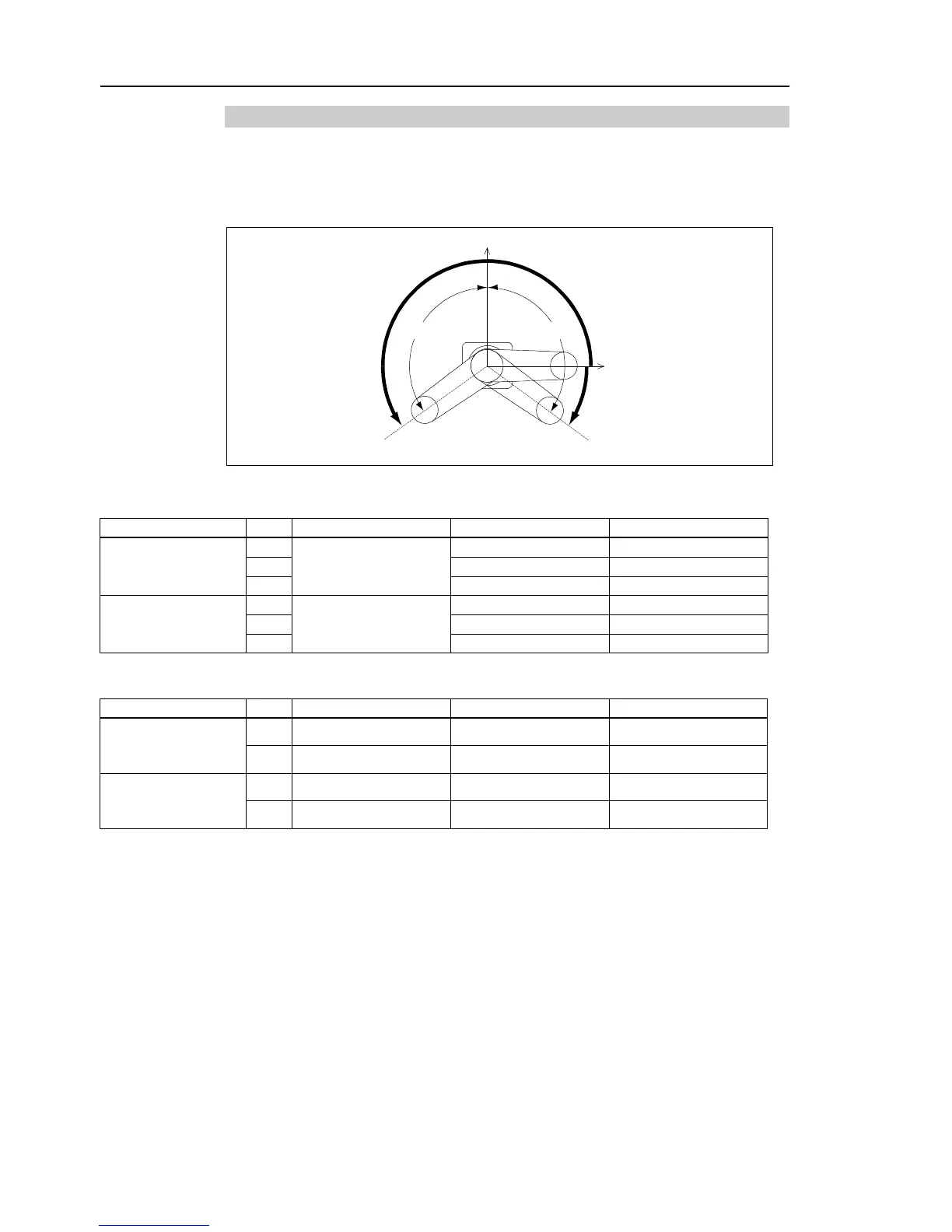
5.1.1 Max. Pulse Range of Joint #1
The 0 (zero) pulse position of Joint #1 is the position where Arm #1 faces toward the
positive (+) direction on the X-coordinate axis.
When the 0 pulse is a starting point, the counterclockwise pulse value is defined as the
positive (+) and the clockwise pulse value is defined as the negative (-).
+Y
+X 0 pulse
+ B
B
+ A
A
Table Top Mounting
Arm
Standard
-R
-L
A
Max. Motion Range
(deg)
25
±140
30
125 ~ 150
150 ~ 125
35
110 ~ 165
165 ~ 110
B
Max. Pulse Range
(pulse)
25
1456356 ~ 6699236
30
1019449 ~ 6990507
1747627 ~ 6262329
35
582542 ~ 7427413
2184533 ~ 5825422
Multiple Mounting
Arm
Standard
-R
-L
A
Max. Motion Range
(deg)
30
±115
35
±120 105 ~ 130 130 ~ 105
B
Max. Pulse Range
(pulse)
30
728178 ~ 5971058
35
873813 ~ 6116693 436907 ~ 6407965 1165085 ~ 5679787

Table of Contents

Questions and Answers:

Question and Answer IconNeed help?

Do you have a question about the Epson G3 Series and is the answer not in the manual?

Epson G3 Series Specifications

General IconGeneral
BrandEpson
ModelG3 Series
CategoryRobotics
LanguageEnglish

Related product manuals