EasyManuals Logo
Home>Epson>Robotics>G3 Series

Epson G3 Series User Manual

Epson G3 Series
200 pages
To Next Page IconTo Next Page
To Previous Page IconTo Previous Page
Page #177 background imageLoading...
Page #177 background image
Maintenance 12. Lithium Battery
G3 Rev.14 165
12.2 Replacing the Battery Board
After battery board and parts have been replaced (motors, reduction gear units, brakes,
timing belts, ball screw spline unit, etc.), the Manipulator cannot operate properly because
a mismatch exists between the origin stored in each motor and its corresponding origin
stored in the Controller.
After replacing the parts, it is necessary to match these origins.
The process of aligning the two origins is called “Calibration”.
Refer to Maintenance: 14. Calibration to perform the calibration.
Battery board
Removal
(1)
Turn
OFF the Controller.
(2)
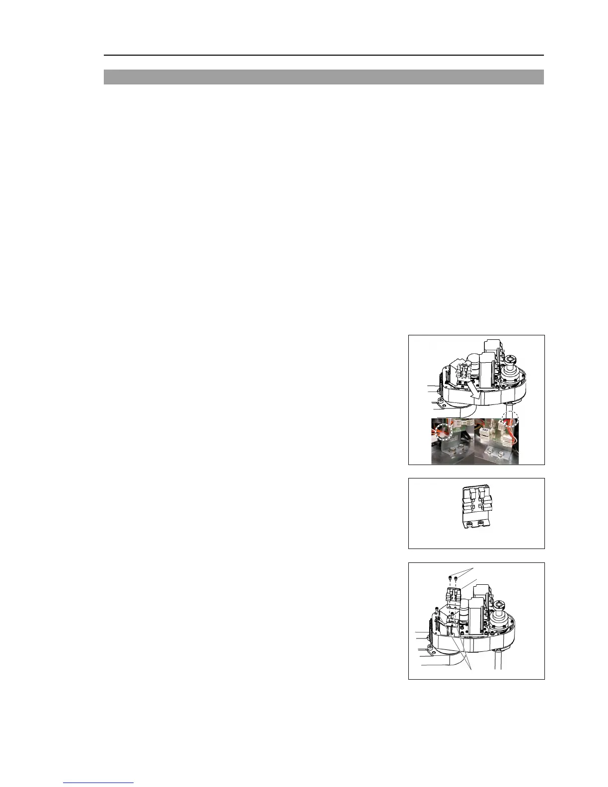
Push down the shaft to its lower limit while pressing the brake release switch. Be
sure to keep enough space and prevent the
end effector
hitting any peripheral
equipment.
The brake release switch
affects only Joint #3. When the brake release switch i
s
pressed, the brake
for Joint #3 is released simultaneously.
Be careful of the
shaft while the brake release switch is being pressed because
the
shaft may be lowered by the weight of an end effector
.
(3)
Remove the arm top cover.
For details, refer to
Maintenance: 3.1 Arm Top Cover.
(4)
Disconnect the wiring tie connecting the
connector cable.
(5)
Disconnect the connectors X61, X62, X63, and
X64
from the battery board.
Battery board
X61
X62
X63
X64
(
6)
Loosen the screws securing the battery board
and remove the
battery board.
2-M4×5
Battery board
2-M4×12

Table of Contents

Questions and Answers:

Question and Answer IconNeed help?

Do you have a question about the Epson G3 Series and is the answer not in the manual?

Epson G3 Series Specifications

General IconGeneral
BrandEpson
ModelG3 Series
CategoryRobotics
LanguageEnglish

Related product manuals