Setup & Operation 3. Environments and Installation
36 G3 Rev.14
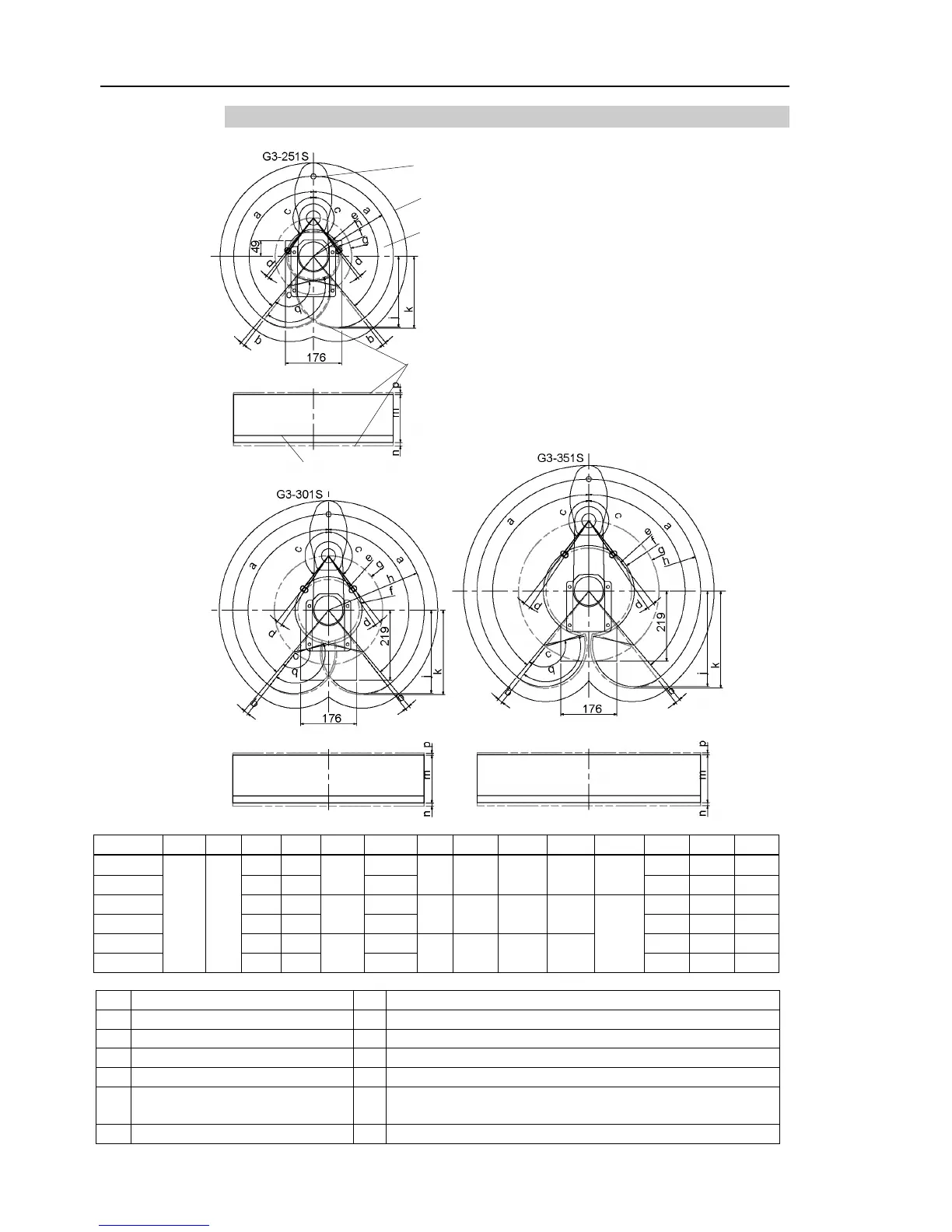
3.3.1 Table Top Mounting – Straight Arm
Area limited by mechanical stop
120 250 221.9 224.5 143.3°
170 300 260.2 263.9
145.8°
Joint #1 angle to hit mechanical stop (degree)
Joint #2 angle to hit mechanical stop (degree)
Joint #3 range to hit lower mechanical stop (mm)
Joint #3 range to hit upper mechanical stop (mm)
Motion range of Joint #1 (degree)
Range from center of axis to back end (mm)
c Motion range of Joint #2 (degree) k
Range from center of axis to back end after moved to
Joint #2 motion range + angle to hit mechanical stop (degree)
 Loading...


