Setup & Operation 3. Environments and Installation
G3 Rev.14 47
3.7 User Wires and Pneumatic Tubes
Only authorized or certified personnel should be allowed to perform wiring.
Wiring by unauthorized
or uncertified personnel may result in bodily injury and/or
malfunction of the robot system.
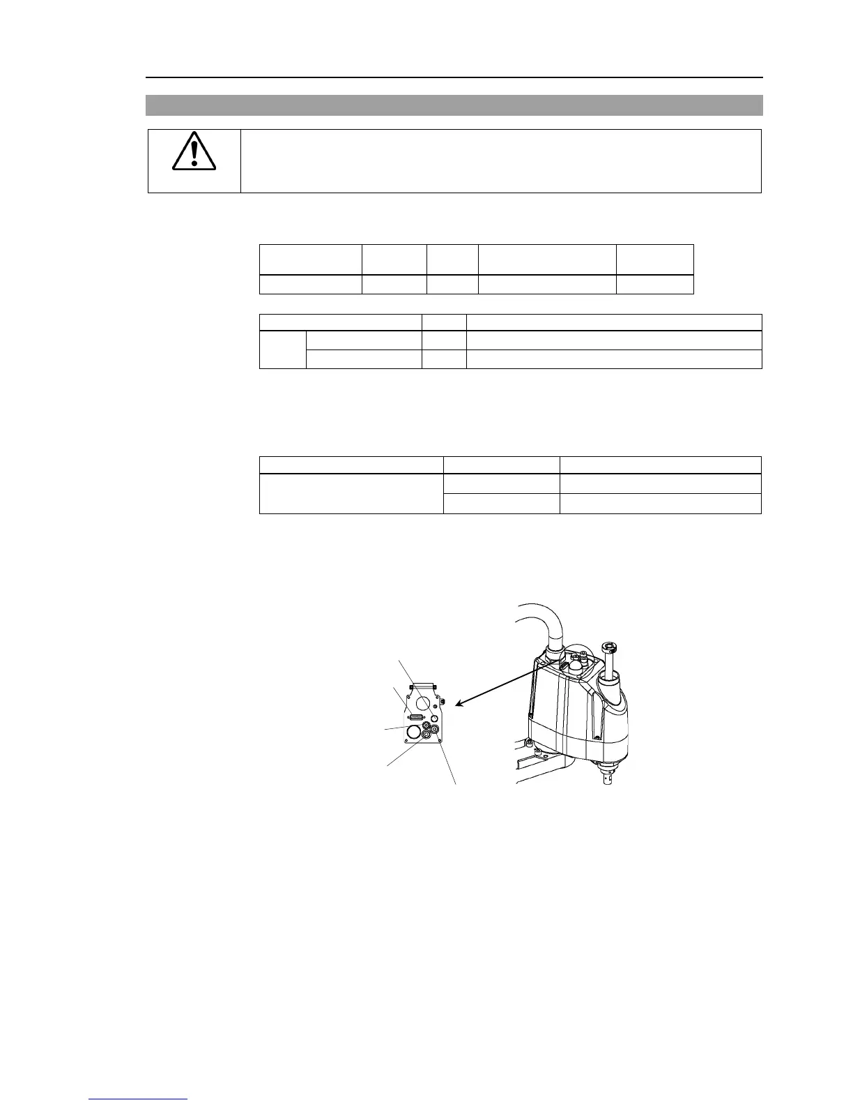
User electrical wires and pneumatic tubes are contained in the cable unit.
Electrical Wires
Rated Voltage
Current
Wires Nominal Sectional Area Note
(Connector setscrew: #4-40 NC)
Pins with the same number, indicated on the connectors on both ends of
the cables, are connected.
Pneumatic Tubes
Max. Usable Pneumatic Pressure
Outer Diameter × Inner Diameter
0.59 MPa (6 kgf/cm
2
: 86 psi)
Fittings for ø6 mm and ø4 mm (outer diameter) pneumatic tubes are supplied on both ends
of the pneumatic tubes.
* Color differs depending on the shipment time
Common Parts
Fitting (white) for
ø6 mm pneumatic tube
Fitting (black or blue)* for
ø6 mm pneumatic tube
Fitting (black or blue)* for
ø4 mm pneumatic tube
 Loading...


