Maintenance 8. Arm #4
134 G3 Rev.14
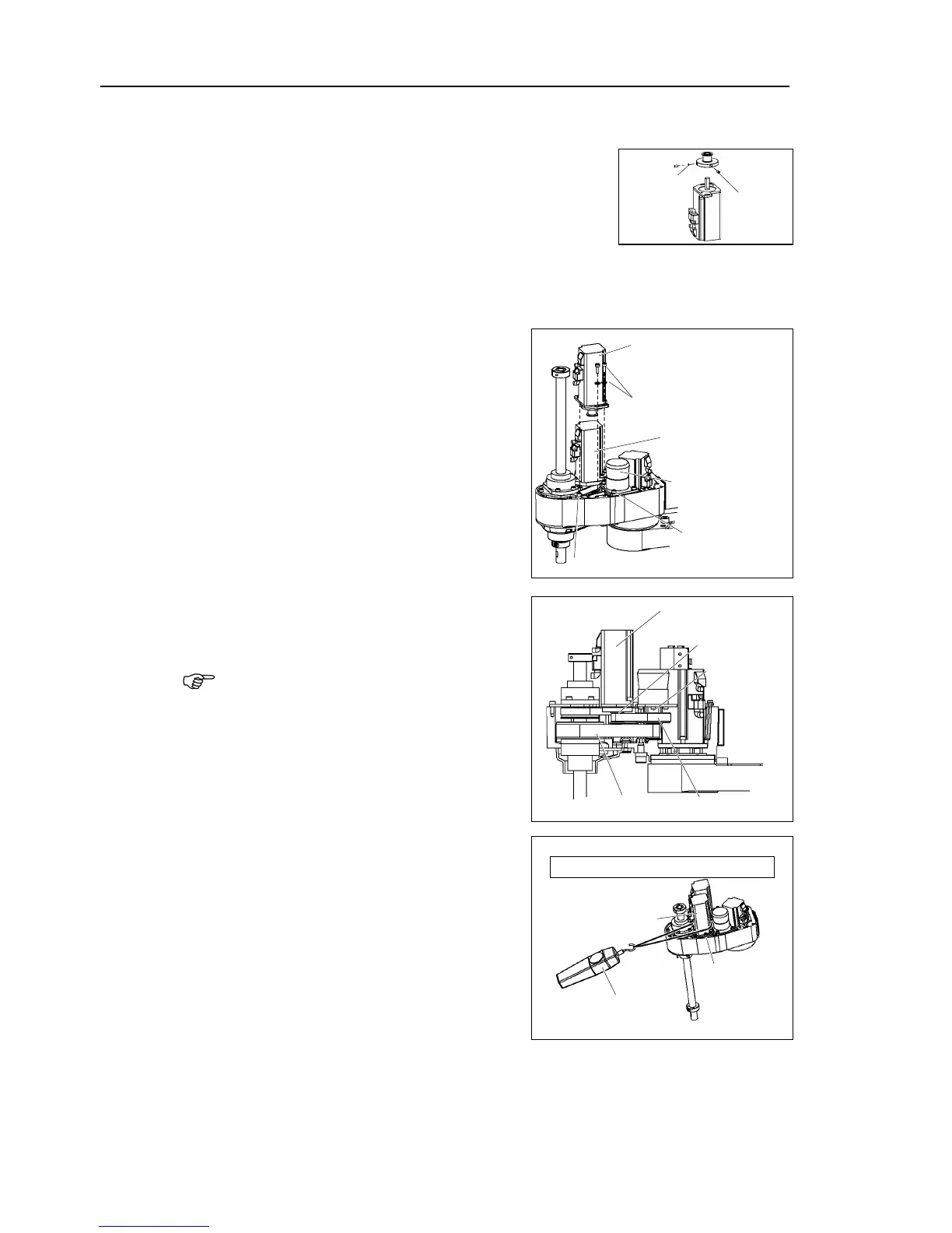
Mount the motor plate to the Joint #4 motor.
Secure the pulley to the new
Be sure to fit the end face of the pulley to
the set screws on the flat face of the
motor shaft until the screw just
Insert a bushing into the other set screw hole to prevent damage to the motor shaft.
Then, tighten
Place the pulley around the U2 belt and
p
lace the Joint #4 motor unit in the arm so
that the motor cable faces toward the
Joint #4
Intermediate shaft
Loosely secure the Joint #4 motor unit to
Arm
the motor unit can be moved
, and it will not tilt when pulled.
f the unit is secured too loose or too tight,
he gear grooves of the belt
are fit into those of the pulleys
Apply the proper tension to the U1 belt
and secure
a suitable cord or string around the
Joint #4 motor unit near its mounting
plate
ull the cord using a force gauge or
similar tool to apply the specified tension
shown in the figure
U1 belt tension = 74 N (7.5 ± 0.5 kgf)
Connectors: X241, X41, X42
 Loading...


