5-32 Disassembly, Assembly, and Adjustment Rev. A
Confidential
Main Assembly 16
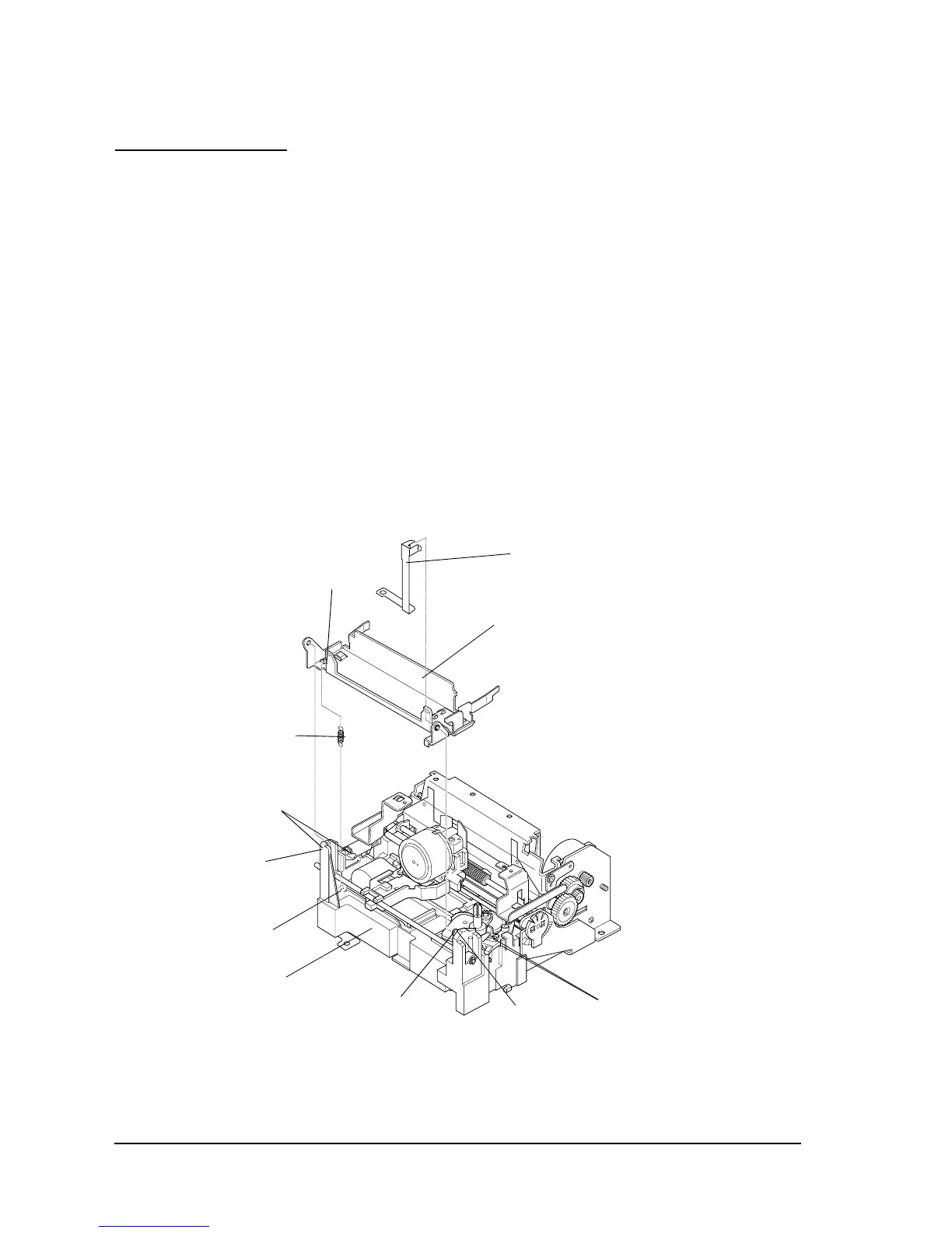
Ribbon frame assembly, ribbon frame spring, and ribbon frame fixing plate
1. Apply G-31 to the switching point of the ribbon frame on the ribbon switch lever. (A line of
lubrication: length 4 mm x wide 1 mm)
2. Apply G-31 to the tip of release point of the ribbon frame assembly on the base frame
assembly. (A point of lubrication: diameter 1 mm)
3. Apply G-31 to the each ribbon frame assembly mounting shaft (left and right) in the base
frame assembly. (A line of lubrication: length 2 mm x wide 1 mm)
4. Attach the shaft (A) and (B) of the base frame assembly to the ribbon frame assembly.
5. Attach the ribbon frame fixing plate into the groove in the right ribbon frame assembly
mounting shaft (A).
6. Hook the ribbon frame spring to (C) of the base frame assembly and (D) of the ribbon frame
assembly.
Ribbon frame fixing plate
Ribbon frame assembly
Ribbon frame spring
Apply G-31
(D)
(C)
Apply G-31
(A)
Apply G-31
Base frame assembly
(B)
 Loading...