2-26 Mechanism Configuration and Operating Principles Rev. A
Confidential
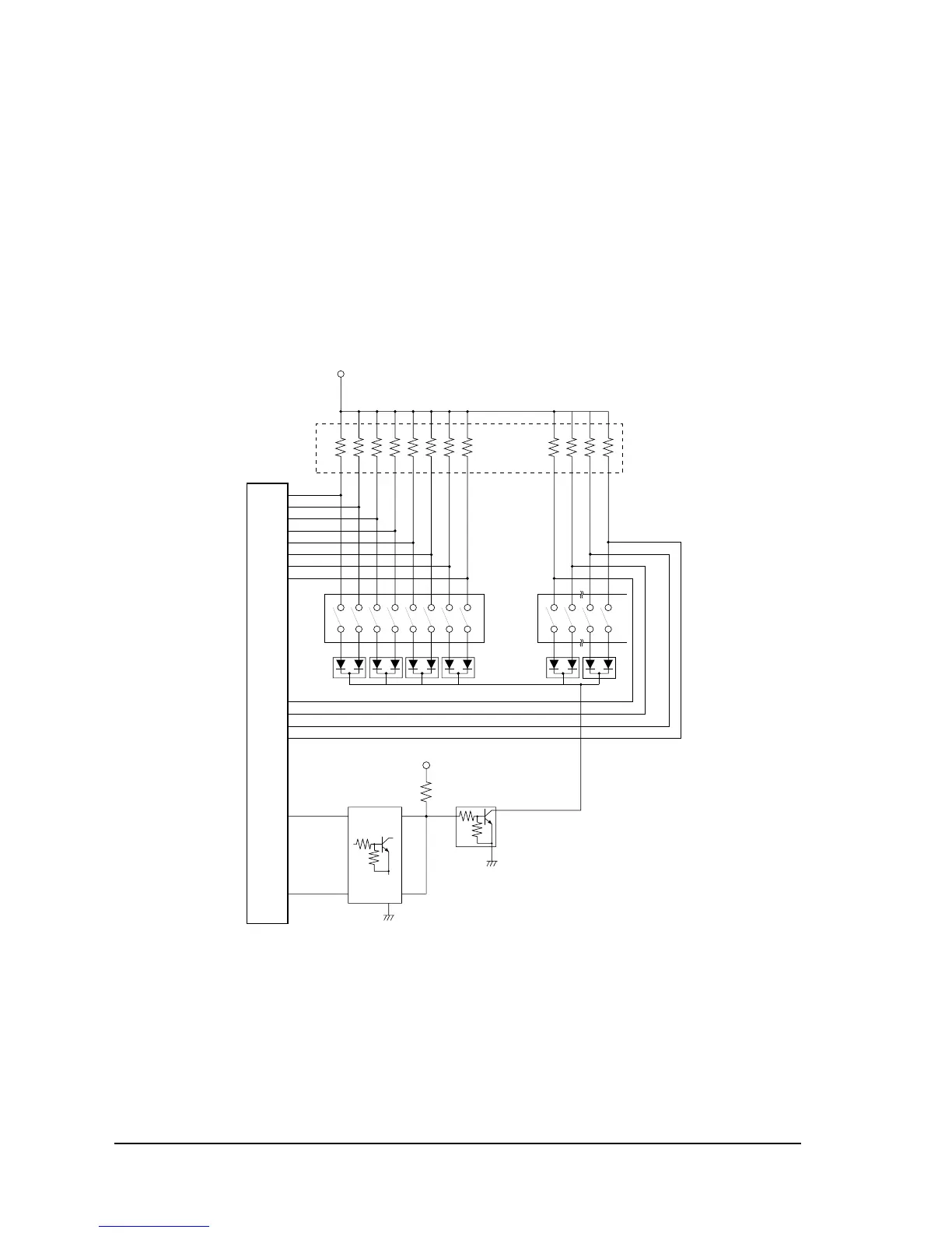
DIP switch read circuit
There are 12 switches in DIP switch bank DSW1 and DSW2 switches in DIP switch bank 2 that
are status-readable switches. Each signal is input to the CPU. The signal is read as
LOW
when
the switch is on, and
HIGH
when the switch is off.
CPU (U5) pins 52 to 55, pins 56 to 59, and pins 1, 27, 28 and 81 are also used for the carriage
motor drive circuit, paper feed motor drive circuit, operation panel control circuit and address
bus. The pins are used to read DIP switches temporarily immediately after the printer
initialization (or the power is turned on).
Figure 2-25 DIP switch read circuit
(*1): Resistance between E and B is used for pull-up resistors in the transistor.
{5V
52
53
54
55
56
57
58
59
P20
P21
P22
P23
P90
P91
P92
P93
12345 768
DSW1
U5
DM101 DM102 DM103 DM104 DM105 DM106
QM
101
QM
102
QM
101
QM
102
QM
103
QM
105
QM
103
RM6 QM
109
QM
109
1256
DSW2
1
80
27
28
P57
P56
P75
P76
QM117QM112
R29
{5 V
3
P100
4
3
5
2
1
4
P101
(1)
 Loading...