EasyManuals Logo
Home>Epson>Printer>TM-U200 Series

Epson TM-U200 Series Technical Manual

Epson TM-U200 Series
187 pages
To Next Page IconTo Next Page
To Previous Page IconTo Previous Page
Page #148 background imageLoading...
Page #148 background image
5-38 Disassembly, Assembly, and Adjustment Rev. A
Confidential
Main Assembly 4 (Case Unit)
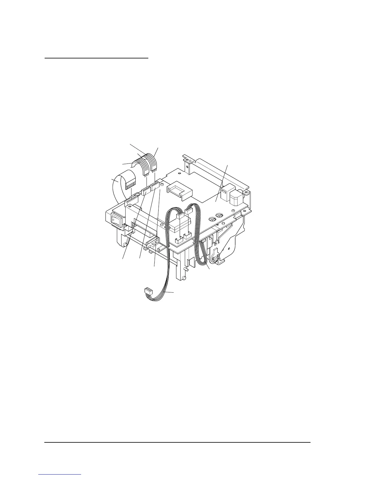
Inserting the cables
1. Insert the lead wires of the print head FPC, the sensor assembly, and the auto-cutter
assembly into the connectors.
2. Insert the paper feed motor cable into CN6 and the carriage motor cable into CN5. At this
time, make sure to insert the cables so that black or red colored side connects to the pin 1
side of each connector.
Make sure not to confuse paper feed motor cable and carriage motor cable. Also check that
the black or red side of each cable is on the pin 1 side of the connector.
Red cable
Black cable
Main circuit
board assembly
Carriage motor cable
Paper feed
motor cable
Print head FPC
CN6
CN5
(Pin 1 side)
Sensor assembly’s lead wires
Auto-cutter assembly’s lead wires

Table of Contents

Other manuals for Epson TM-U200 Series

Questions and Answers:

Question and Answer IconNeed help?

Do you have a question about the Epson TM-U200 Series and is the answer not in the manual?

Epson TM-U200 Series Specifications

General IconGeneral
BrandEpson
ModelTM-U200 Series
CategoryPrinter
LanguageEnglish

Related product manuals