Rev. A Disassembly, Assembly, and Adjustment 5-39
TM-U200 Series (Type A/AM) Technical Manual
Confidential
Main Assembly 5 (Case Unit)
Lower case assembly
CAUTION:
Never disassemble the take-up holder plate. If you disassemble it, operation of this unit
can not be guaranteeed.
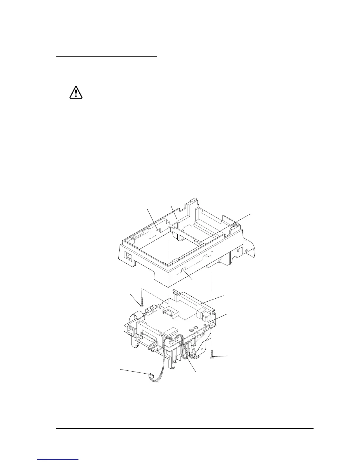
1. Attach the lower case to the printer mechanism assembly. It is easy to assemble if you first
place portion B of the lower case under portion A of the upper plate.
2. Bring out the paper feed motor and carriage motor cables through portion C and the sensor
assembly lead wires through portion D.
3. Secure the lower case with the screws.
[Adjustment]
Perform the platen gap adjustment by referring to the Adjustment section at the end of this chapter.
Portion B
Lower case
Portion C
Upper plate
Portion D
Portion A
CPT-B (M3x12)
[0.59 to 0.78 N • m
[6 to 8 kgf • cm)]
Sensor assembly’s lead wires
CPT-B (M3x12)
[0.59 to 0.78 N • m
[6 to 8 kgf • cm)]
Auto-cutter assembly’s lead wires
 Loading...