2-28 Mechanism Configuration and Operating Principles Rev. A
Confidential
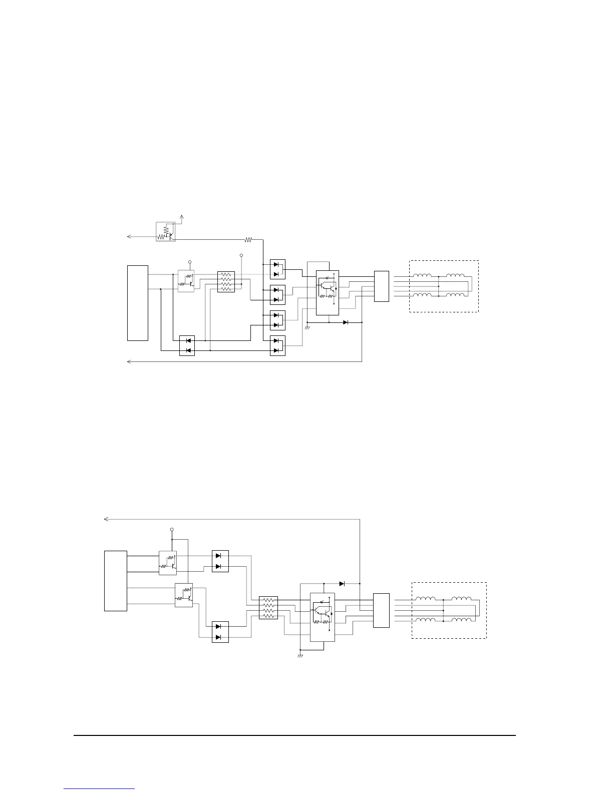
Paper feed motor driver circuit
The paper feed motor (stepping motor) possesses an accurate angle of rotation and permits
speed control. It is driven with 2-2 phase excitation. By turning P53 of the CPU to LOW, +24 V
(labeled +24C signal in the figure below) is applied to the COM terminal of its coil, and it is
made to run by changing P90 and P92 to HIGH and LOW. Its speed is determined by the speed
of changing P90 and P92 between HIGH and LOW. At the end of paper feeding, P53 of the CPU
is once again set to HIGH.
Figure 2-27 Paper feed motor driver circuit
Carriage motor driver circuit
The carriage motor (stepping motor) possesses an accurate angle of rotation and permits speed
control. It is driven with 2-2 phase excitation. By turning P52 of the CPU to LOW, +24 V (labeled
+24B signal in the figure below) is applied to the COM terminal of its coil, and it is made to run
by changing P20, P21, P22, and P23 to HIGH and LOW. Its speed is determined by the speed of
changing P20, P21, P22, and P23 between HIGH and LOW. At the end of paper feeding, P52 of
the CPU is once again set to HIGH.
Figure 2-28 Carriage motor driving circuit
Q113
9
7
5
3
8
6
4
2
1
1
2
3
1
0
QM4
DM107
R102
1
2
3
1
2
3
CN6
4
5
4
5
nPFCOM
PF C/DSW7
PF C/DSW7
PF A/DSW5
PF A
PF C
PF COM
PF B
PF D
+24C
D10
(ROTOR)
+5V
+24C
U5
56
58
P90/M10
P92/M12
Ł[^
4
1
2
5
3
QM103
DM122
+5V
RM104
81
72
63
54
1
2
3
DM108
1
2
3
DM109
1
2
3
DM110
+5V
Paper feed motor
CR A/DSW1
CR C/DSW3
CR B/DSW2
CR D/DSW4
RM104
81
72
63
54
9
7
5
3
8
6
4
2
1
1
0
QM3
1
2
3
1
2
3
CN5
4
5
4
5
CR A
CR C
CR COM
CR B
CR D
+24B
D9
(ROTOR)
+24B
U5
52
54
53
55
P20/M00
P22/M02
P21/M01
P23/M03
LbW[^
DM120
DM121
4
1
24
3
1
2
4
3
1
2
5
3
QM101
+5V
4
1
2
5
3
QM102
Carriage motor
 Loading...