2-12 Mechanism Configuration and Operating Principles Rev. A
Confidential
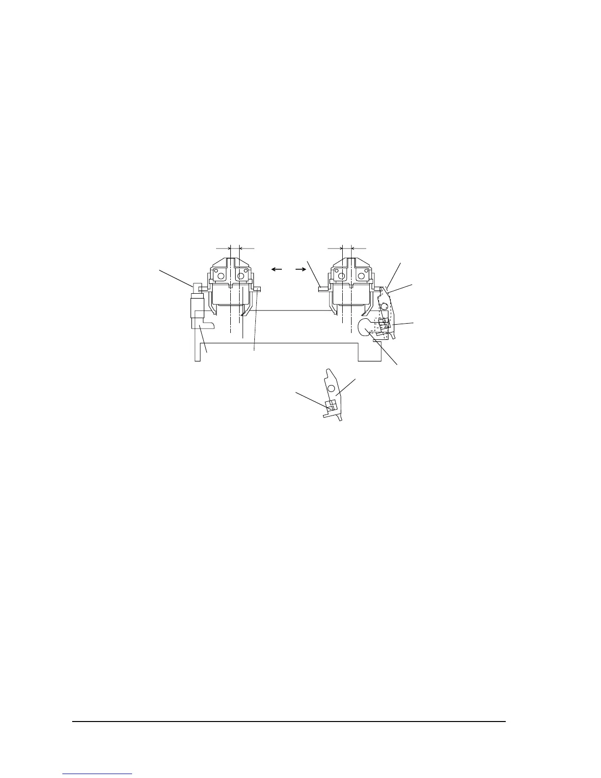
Releasing from Red to Black
When the carriage sub assembly moves in the D direction and reaches the ribbon release area,
the ribbon release lever is pushed by the ribbon release section. Then portion C pushes the
ribbon frame assembly upward. At this time, the detent face for the ribbon switch is released
from the ribbon switch lever hole in the ribbon frame assembly and the ribbon switch lever is
returned to ribbon switch lever position B (shown by the solid lines) by the spring power of the
ribbon release spring. When the carriage sub assembly moves in the E direction, the ribbon
frame assembly and ribbon release lever return to their original positions because of the spring
power of the ribbon frame spring.
Figure 2-15 Ribbon Switching
Ribbon switch lever
Ribbon switch lever hole
A
B
Detent face for ribbon switch
Push face for ribbon frame
C
E
D
Ribbon release lever
Ribbon release range Ribbon switch range
Ribbon switch section
Ribbon release section
 Loading...