Translation of the original instructions
EN GL IS H
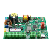
external
internal
Example: configuration with 2 infrared detectors at the exit.
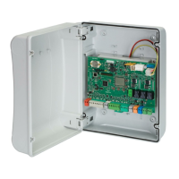
infrared 1 and 2
infrared 1 and 2
Infrared technology detectors connection
red 1 and 2
pink
pink
blue 1 and 2
grey
grey
green 1 and 2
brown 1 and 2
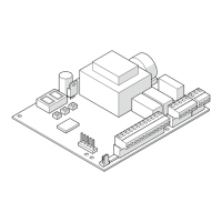
INFRARED DETECTOR FOR SAFETY IN OPENING
!
It is obligatory to install protective barriers in the movement areas in
the event contact with persons is not allowed.
i
Use this configuration to protect the opening movement space by
means of safety detectors.
The XBFA ON infrared detectors allow safety in opening in compliance
with EN 16005:2012 and DIN18650.
The default programming of the E1SL corresponds to the typical example
configuration shown in the figure.
from Board from SDK EVO
o1 = 5
Inputs O1
01 Function = TEST
01 NO/NC = NO (only via the SDK EVO)
C3 = 21
3F
= Y
INPUTS I3-I4
I3 = Safety on opening
I3 NO/NC = NC
I3 TEST = Enabled
C4 = 21
4F
= Y
I4 = Safety on opening
I4 NO/NC = NC
I4 TEST = Enabled
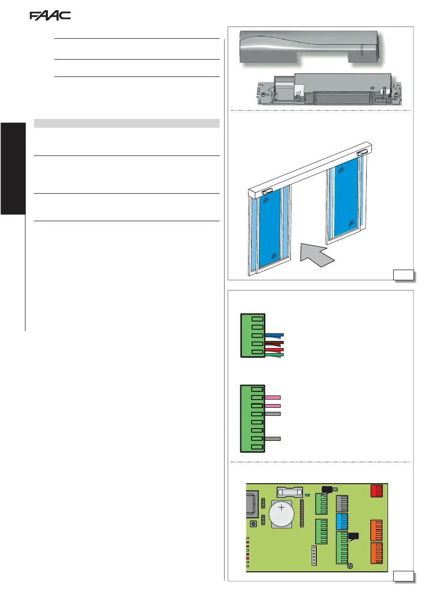
1. With the board switched off, connect the detectors. Follow the colour
coding of the wiring shown in the figure.
2. Turn power on to the E1SL board. The detectors turn on.
3. Carry out the SETUP procedure for each detector (see the device
instructions).
4. If necessary, program the configurable inputs on the automation
board differently.
- from Board: Basic Programming for the inputs of terminal board J21. Advanced
Programming for the inputs of terminal board J22.
or
- from SDK EVO:
/PROGRAMMING/INPUTS OUTPUTS…
…OUTPUTS O1-O2
…INPUTS I1-I4
5. Check for correct operation.

 Loading...