+ R2
GND
+ R1
+ T2
GND
+ T1
J9
Translation of the original instructions
EN GL IS H
blueblue
blue
blue
blue
blue
blackblack
black
grey
grey
grey
black
black
black
grey
grey
grey
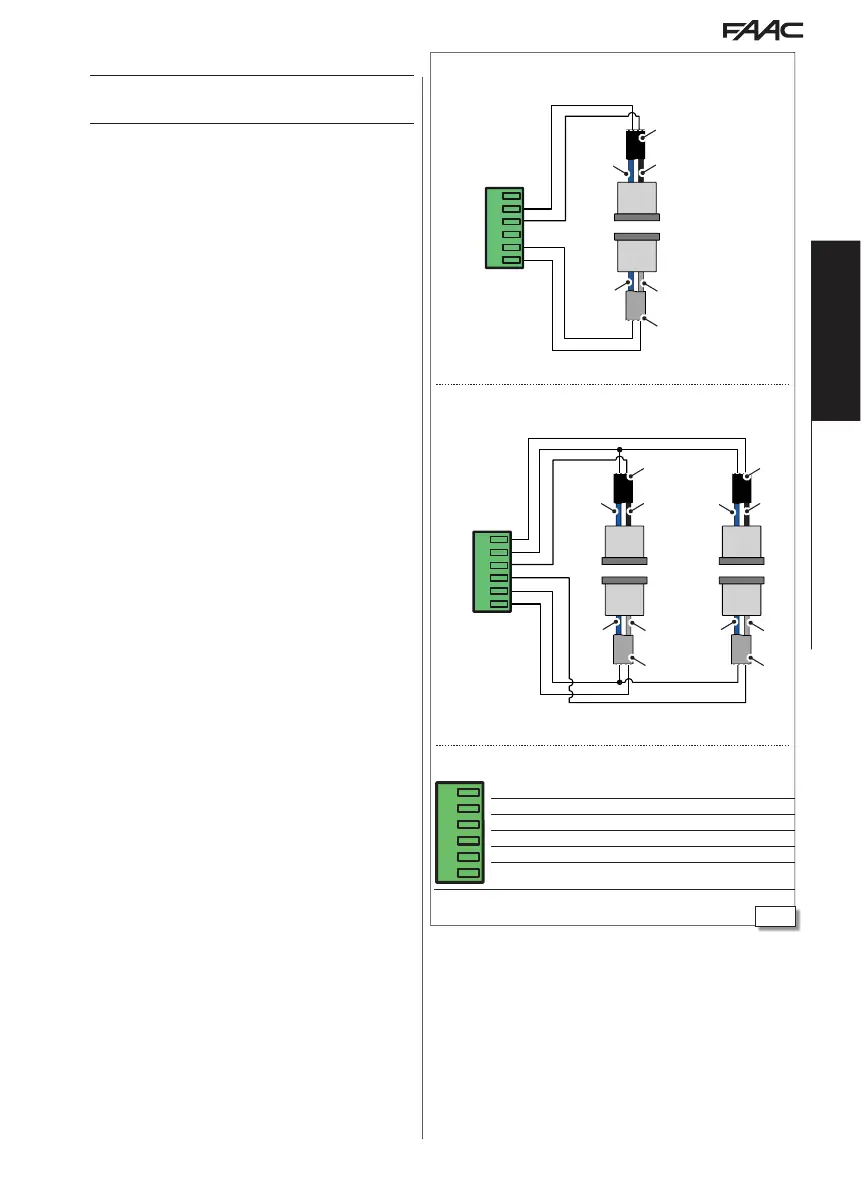
2 Pairs of button photocells connection
1 Pair of button photocells connection
XFA BUTTON PHOTOCELLS
!
Photocells are not permitted as safety devices in European Community
countries in which the EN 16005:2012 standard is in force. Specifically,
photocells are considered as auxiliary devices, complementary to safety.
The button photocells are active during CLOSING.
1. Connect the photocells.
CABLE colour
TX - transmitter grey and blue (grey sheath)
RX - receiver black and blue (black sheath)
Note: leave the inputs of the connector free if button photocells are
not used.
2. Enable the photocells.
- from Board: advanced programming
bP = 1 1 pair
bP = 2 2 pairs
or
- from SDK EVO:
/PROGRAMMING/INPUTS OUTPUTS/PHOTOCELLS XFA 1 PAIR or 2 PAIRS
J9
R2 2nd pair receiver connection
G GND Receiver negative
R1 1st pair receiver connection
T2 2nd pair transmitter connection
G GND Transmitter negative
T1 1st pair transmitter connection

 Loading...