FEASA LED ANALYSER
FUNCTIONAL VERSION
Daisy Chain Mode
Daisy Chain Serial RS232 Wiring Method:
The Daisy chain is a method used to communicate with multiple Led Analyser units to save
connections and simplify the wiring.
The 1
st
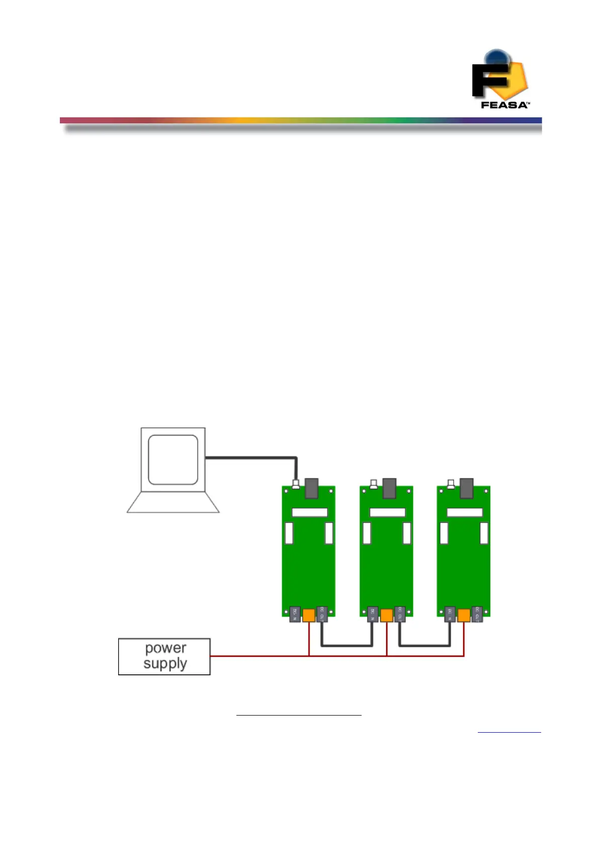
Led analyser in the chain is connected to the computer using the Serial cable supplied.
The remaining LED Analysers are interconnected in a Daisy Chain Bus using the cables
provided. The Daisy Chain OUT connector on Led Analyser No1 is connected to the Daisy Chain
IN Connector on Led Analyser No2 and so on.( See Fig 9b below). Each Analyser must be
powered to 5V @220mA. This completes your wiring requirements.
Please Ensure the RS232 GND (pin3) and the PSU GND are
connected together.
Figure 9b Serial Setup
Back to Index
104