FEASA LED ANALYSER
FUNCTIONAL VERSION
Daisy Chain Mode
Ports Description and Wiring.
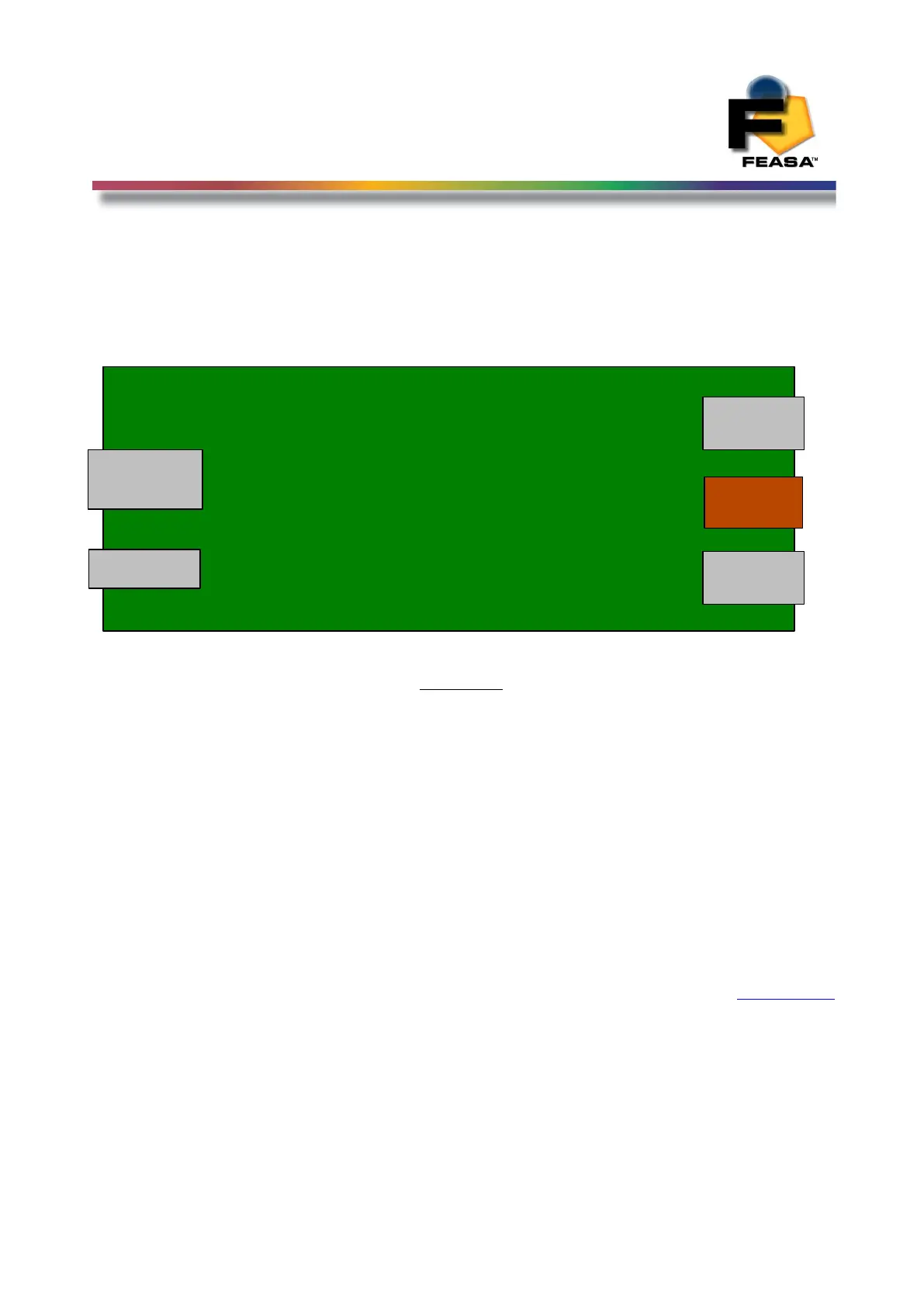
Figure 10
The Daisy Chain Connectors are shown on the right-hand side of figure 10.
The D_OUT connector is connected to the D_IN connector of the next Analyser in the chain.
The Power Connector is used to supply +5V DC to each Analyser in the chain.
Allow 220mA @5V for each Analyser and ensure the wiring is adequate to supply the current
without incurring large voltage drops. For reliable operation it is necessary to have 5V
at the Power Connector of each Analyser. Do not exceed 6V for a prolonged period as this
will damage the Analyser.
Back to Index
112
D_OUT
D_IN
1
2
3
1
2
3
Power
0V
5V
USB
Serial