EasyManua.ls Logo

Fuji Electric frenic mini series User Manual

Fuji Electric frenic mini series
306 pages
To Next Page IconTo Next Page
To Previous Page IconTo Previous Page
Page #106 background imageLoading...
Page #106 background image
6.3 Peripheral Equipment
6-9
Chap. 6 SELECTING PERIPHERAL EQUIPMENT
Table 6.5 Rated Current of Molded Case Circuit Breaker/Ground-Fault Circuit Interrupter and
Magnetic Contactor
w/ DCR w/o DCR w/ DCR w/o DCR
1/8
FRNF12C1
-2U
1/4
FRNF25C1
-2U
5 (6)
1/2
FRNF50C1
-2U
1
FRN001C1
-2U
10 SC-05 SC-05
2
FRN002C1
-2U
15 (16)
3
FRN003C1
-2U
20 (25)
5
FRN005C1
-2U
20 (25) 30 (35) SC-5-1
1/2
FRNF50C1
-4U
1
FRN001C1
-4U
2
FRN002C1
-4U
10 SC-05 SC-05 SC-05
3
FRN003C1
-4U
15 (16)
5
FRN005C1
-4U
10 20 (25)
1/8
FRNF12C1
-7U
1/4
FRNF25C1
-7U
5 (6)
1/2
FRNF50C1
-7U
10 SC-05
1
FRN001C1
-7U
10 15 (16)
2
FRN002C1
-7U
15 (16) 20 (25)
3
FRN003C1
-7U
20 (25) 30 (35) SC-5-1
SC-05SC-05
SC-05
5 (6)
10
5 (6)
5 (6)
5 (6)
Power
supply
voltage
Three-
phase
230 V
Three-
phase
460 V
Single-
phase
230 V
Magnetic contactor type
MC2 (for output circuit)
Applicable
motor
rating
(HP)
MCCB, GFCI
Rated current (A)
Magnetic contactor type
MC1 (for input circuit)
DC reactor (DCR)
Inverter type
DC reactor (DCR)
- The above table lists the rated current of MCCBs and GFCIs to be used in the power control cabinet with an
internal temperature of lower than 50qC (120qF). The rated current is factored by a correction coefficient of
0.85 as the MCCBs' and GFCIs' original rated current is specified when using them in an ambient
temperature of 40qC (104qF) or lower. Select an MCCB and/or GFCI suitable for the actual short-circuit
breaking capacity needed for your power systems.
- For the selection of the MC type, it is assumed that the 600V HIV (allowable ambient temperature:
75
q
C (167
q
F)) wires for the power input/output of the inverter are used. If an MC type for another class
of wires is selected, the wire size suitable for the terminal size of both the inverter and the MC type
should be taken into account.
- Use GFCIs with overcurrent protection.
- To protect your power systems from secondary accidents caused by the broken inverter, use an MCCB
and/or GFCI with the rated current listed in the above table. Do not use an MCCB or GFCI with a rating
higher than that listed.
Notes: 1) A box (
) in the above table replace S or E depending on enclosure.
2) Values in parentheses ( ) in the above table denote rated currents for the European version.

Table of Contents

Other manuals for Fuji Electric frenic mini series

Question and Answer IconNeed help?

Do you have a question about the Fuji Electric frenic mini series and is the answer not in the manual?
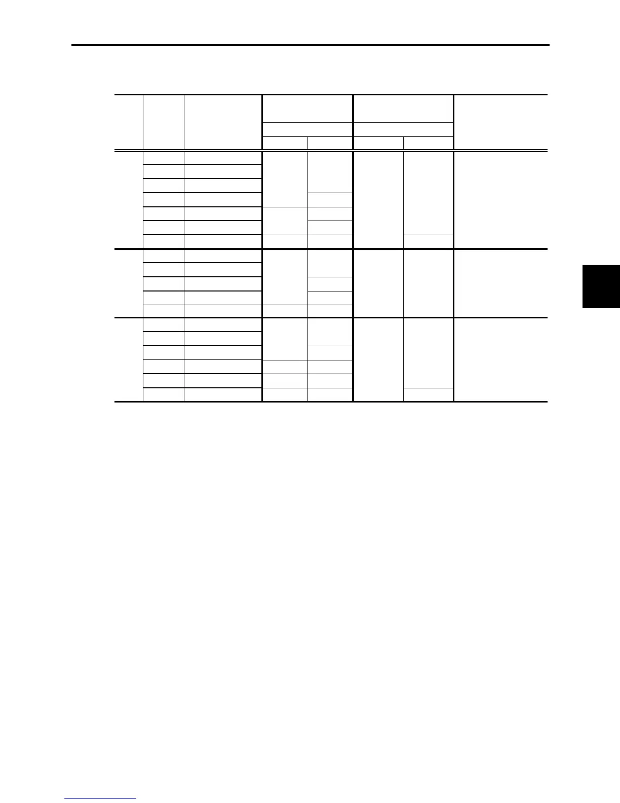
Fuji Electric frenic mini series Specifications

General IconGeneral
Output Frequency0.1 to 400 Hz
Control MethodV/F control, Sensorless vector control
Cooling MethodFan cooling
ModelFrenic Mini series
Overload Capacity150% for 60 seconds
ProtectionOvercurrent, Overvoltage, Undervoltage, Overheating, Short circuit
CommunicationRS-485 (Modbus RTU)
Ambient Temperature-10°C to +50°C (non-freezing)
Humidity95% (non-condensing)
AltitudeUp to 1000 m above sea level
Input Voltage200 to 240 VAC, 380 to 480 VAC
Braking UnitBuilt-in (optional external for higher power models)

Summary

Chapter 1 INTRODUCTION TO FRENIC-Mini

1.1 Features

Details key inverter features like optimum performance, braking resistor, and stable operation.

Chapter 3 OPERATION USING THE KEYPAD

3.2 Running Mode

Details how to run/stop the motor, set frequency, and monitor running status.

3.3 Programming Mode

Covers setting function codes, checking data, monitoring status, and maintenance info.

3.4 Alarm Mode

Explains how the inverter enters Alarm mode and handles alarm conditions.

Chapter 4 BLOCK DIAGRAMS FOR CONTROL LOGIC

Chapter 5 RUNNING THROUGH RS-485 COMMUNICATION (OPTION)

Chapter 6 SELECTING PERIPHERAL EQUIPMENT

Chapter 7 SELECTING OPTIMAL MOTOR AND INVERTER CAPACITIES

7.1 Selecting Motors and Inverters

Guides on selecting motors and inverters considering load and operational requirements.

7.2 Selecting a Braking Resistor

Provides a procedure for selecting appropriate braking resistors based on requirements.

Chapter 8 SPECIFICATIONS

8.8 Details of Protective Functions

Explains various protective functions, their LED displays, and related function codes.

Chapter 9 FUNCTION CODES

9.1 Function Code Tables

Provides tables summarizing function codes, their data ranges, and settings.

9.2 Details of Function Codes

Offers detailed explanations for each function code group (F, E, C, P, H, J, y).

Related product manuals