8.7 Connection Diagrams
8-33
Chap. 8 SPECIFICATIONS
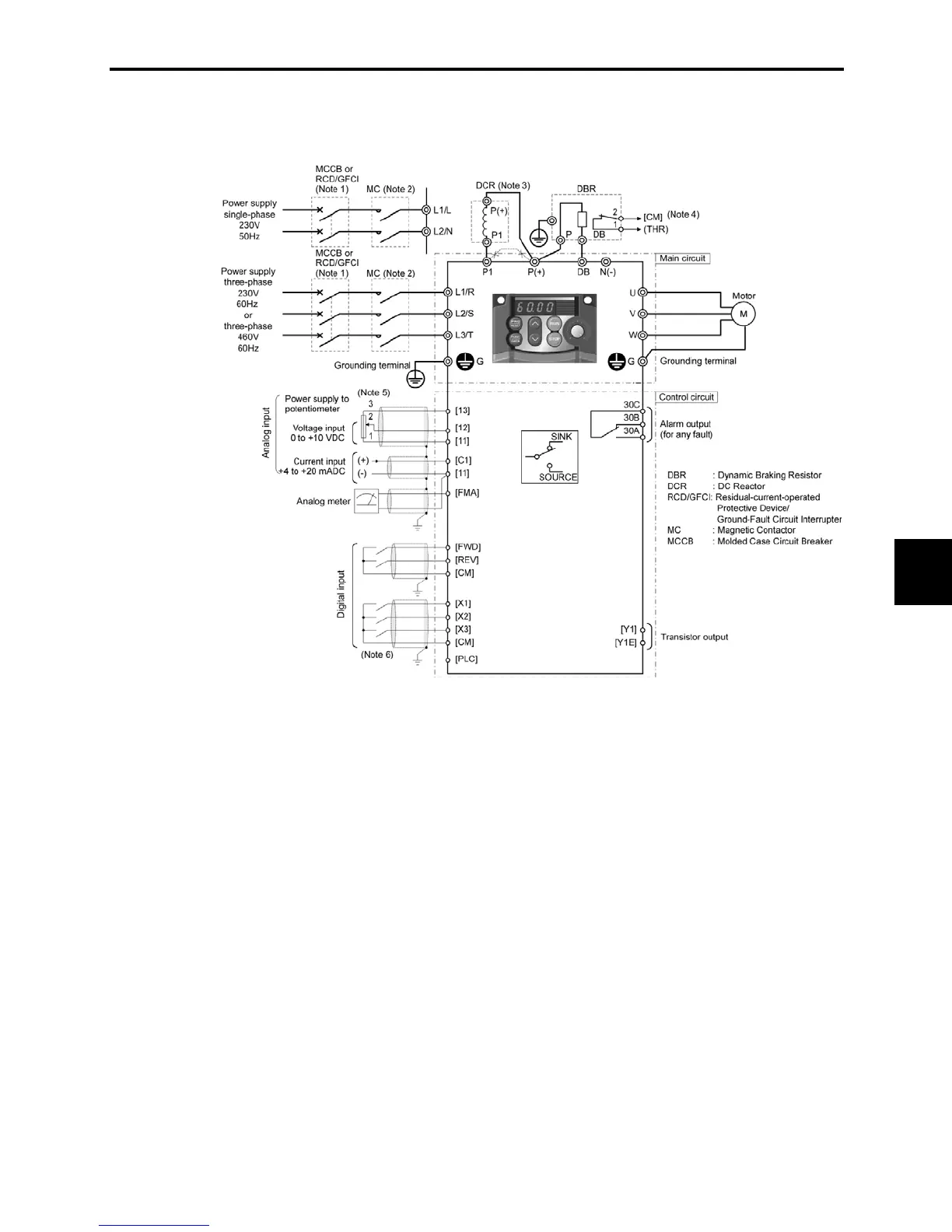
8.7.2 Operation by external signal inputs
The basic connection diagram below shows an example for operation by external input signals.
(Note 1) Install a recommended molded case circuit breaker (MCCB) or a residual-current-operated protective device (RCD)/a
ground-fault circuit interrupter (GFCI) (with overcurrent protection) in the primary circuit of the inverter to protect wiring. At
this time, ensure that the circuit breaker capacity is equivalent to or lower than the recommended capacity.
(Note 2) A magnetic contactor (MC) should, if necessary, be mounted independent of the MCCB or GFCI to cut off the power fed to the
inverter. Refer to page 6-7 for details. MCs or solenoids that will be installed close to the inverter require surge absorbers to be
connected in parallel to their coils.
(Note 3) When connecting a DC reactor (optional accessory), remove the jumper bar from terminals [P1] and [P+].
(Note 4) (THR) function can be used by assigning code "9" (Alarm from external equipment) to any of terminals [X1] to [X3], [FWD] or
[REV] (function code E01 to E03, E98, or E99). For details, refer to Chapter 9.
(Note 5) Frequency can be set by connecting a frequency setting device (external potentiometer) between the terminals [11], [12], and
[13] instead of inputting voltage signal (0 to +10 VDC or 0 to +5 VDC) between the terminals [12] and [11].
(Note 6) For the wiring of the control circuit, use shielded or twisted wires. When using shielded wires, connect the shields to earth. To
prevent malfunction due to noise, keep the control circuit wiring away from the main circuit wiring as far as possible
(recommended: 3.94 in (100 mm) or longer), and never set them in the same wire duct. When crossing the control circuit wiring
with the main circuit wiring, set them at right angles.
 Loading...


