2.1 External View and Allocation of Terminal Blocks
2-1
Chap. 2 PARTS NAMES AND FUNCTIONS
2.1 External View and Allocation of Terminal Blocks
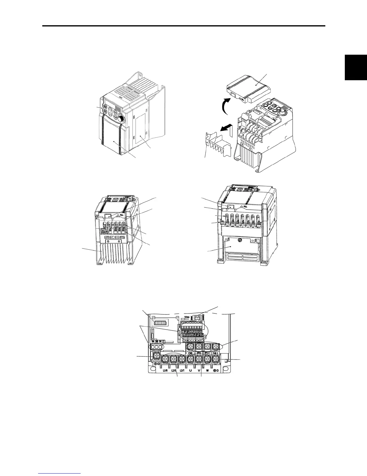
Figures 2.1 and 2.2 show the external and bottom views of the FRENIC-Mini.
(1) External and bottom views
Figure 2.1 External Views of FRENIC-Mini
(a) FRN001C1S-2U (b) FRN002C1S-2U
(*When connecting the RS-485 communications cable, remove the control circuit terminal block cover and snip off the barrier provided
in it using nippers.)
Figure 2.2 Bottom View of FRENIC-Mini
(2) Allocation of terminals
(FRN002C1S-2U)
Figure 2.3 Enlarged View of the Terminal Blocks
The above figures show three-phase power source models. The terminal allocation of the power input
terminals L1/R, L2/S, L3/T, and grounding terminals for single-phase models differs from that shown in
above figures.
Refer to Chapter 8 "SPECIFICATIONS" for details on terminal functions, allocation and
connection and to Chapter 6, Section 6.2.1 "Recommended wires" when selecting wires.
For details on the keys and their functions, refer to Section 2.2 "LED Monitor, Potentiometer and
Keys on the Keypad." For details on keying operation and function code setting, refer to Chapter 3
"OPERATION USING THE KEYPAD."
Keypad
Nameplate
Control circuit terminal
bock cover
Control circuit terminal
block cover
Main circuit terminal
block cover
RS-485 communications card
connector
SINK/SOURCE jumper switch
Grounding terminal
Grounding terminal
Control circuit terminal
block
Power input terminal block
Inverter output terminal block
DC reactor, braking resistor and
DC link bus terminal block
Barrie
for the RS-485
communications port*
Control circuit wire port
Cooling fan
L1/R, L2/S, L3/T, P1, P (+),
N(-) wire port
L1/R, L2/S, L3/T, U, V, W,
grounding wire port
DB, U, V, W,
grounding wire
port
Heat sink
DB, P1, P (+) and N (-) cable port

 Loading...


