3-14
3.3.3 Monitoring the running status--"Drive Monitoring"
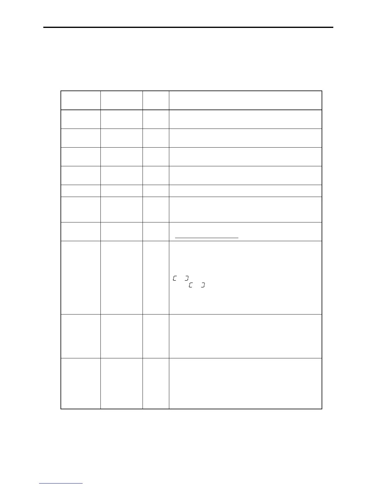
Menu #3 "Drive monitoring" is used to check the running status during maintenance and test running.
The display items for "Drive monitoring" are listed in Table 3.5. Using keys, you may check those items
in succession. Figure 3.7 shows the status transition diagram for "Drive monitoring."
Table 3.5 Drive Monitoring Display Items
LED monitor
shows:
Contents Unit Description
A
Output
frequency
Hz Output frequency before slip compensation
A
Output
frequency
Hz Output frequency after slip compensation
A
Output
current
A Present output current
A
Output
voltage
V Present output voltage
A
Set frequency Hz Present set frequency
A
Rotational
direction
N/A
Displays the rotational direction specified by a run
command being outputted.
H
: forward;
T
: reverse, –
–
–
–: stop
A
Running
status
N/A
Displays the running status in hex. format. Refer to
"Displaying running status
" on the page 3-16.
A
Load shaft
speed
(line speed)
r/min
(m/min)
The unit for load shaft speed is r/min and that for line speed
is m/min.
Display value = (Output frequency Hz before slip
compensation) u (Function code E50)
is displayed for 10000 (r/min or m/min) or more.
When
is displayed, the data is overflowing, which
means that the function code should be reviewed. For
example:
Load shaft speed = Displayed data u 10 (r/min)
A
PID process
commands
N/A
These commands are displayed through the use of function
code E40 and E41 (PID display coefficient A and B).
Display value = (PID process command) u (PID display
coefficient
A - B) + B
If PID control is disabled, "–
–
–
–" appears.
A
PID feedback
value
N/A
This value is displayed through the use of function code
E40 and function code E41 (PID display coefficient A and
B).
Display value = (PID feedback value) u (PID display
coefficient
A - B) + B
If PID control is disabled, "–
–
–
–" appears.
 Loading...


