5.1 Overview on RS-485 Communication
5-3
Chap. 5 RUNNING THROUGH RS-485 COMMUNICATION (OPTION)
5.1.2 Connector specifications
The RS-485 communications card is equipped with an RJ-45 connector whose pin assignment is listed in
the table below.
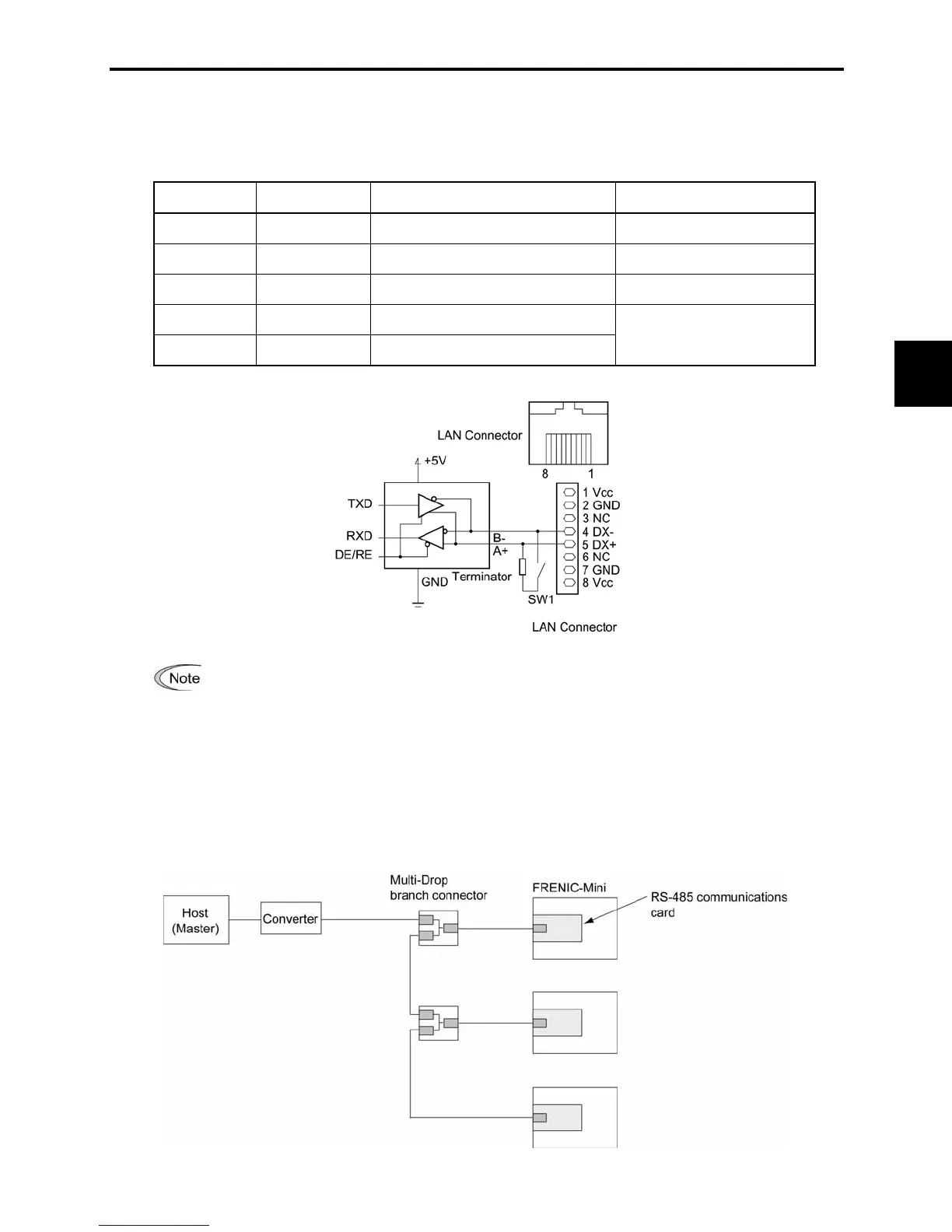
Pin Signal name Function Remarks
1 and 8 Vcc Power source for the remote keypad 5V
2 and 7 GND Reference voltage level GND
3 and 6 NC Not used.
4 DX- RS-485 data (-)
5 DX+ RS-485 data (+)
Built-in terminator: 112 :
Open/close by SW1
The RJ-45 connector has power source pins (pins 1 and 8) designed for the remote keypad.
When connecting other devices to the RJ-45 connector, take care not to use those pins.
Failure to do so may cause a short-circuit.
5.1.3 Connection
You need to select devices suitable for your network configuration, referring to the figure shown below.

 Loading...


