7-10
(3) For a load running horizontally
Assume a carrier table driven by a motor as shown in Figure 7.7. If the table speed is X (m/s) when the
motor speed is N
M
(r/min), then an equivalent distance from the rotation axis is equal to 60·X / (2S·N
M
) m.
The moment of inertia of the table and load to the rotation axis is calculated as follows:
)mkg()WW()
N
ʌ2
ȣ60
(J
2
0
2
M
xx
x
x
(7.9)
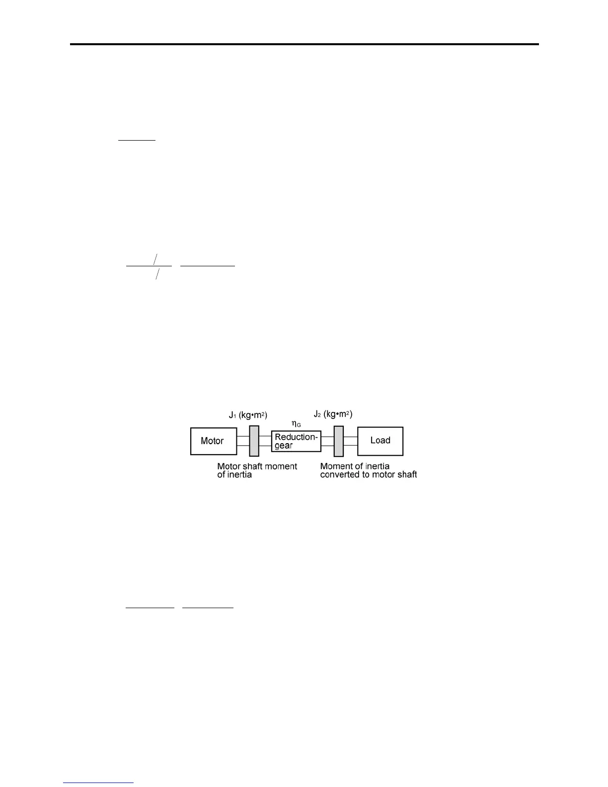
[ 2 ] Calculation of the acceleration time
Figure 7.9 shows a general load model. Assume that a motor drives a load via a reduction-gear with
efficiency K
G
. The time required to accelerate this load to a speed of N
M
(r/min) is calculated with the
following equation:
)s(
60
)0
N
(2
JJ
t
M
G
LM
G
21
ACC
S
W
W
x
x
K
K
(7.10)
where,
J
1
: Motor shaft moment of inertia (kg·m
2
)
J
2
: Load shaft moment of inertia converted to motor shaft (kg·m
2
)
W
M
: Minimum motor output torque in driving motor (N·m)
W
L
: Maximum load torque converted to motor shaft (N·m)
K
G
: Reduction-gear efficiency.
As clarified in the above equation, the equivalent moment of inertia becomes (J
1
+J
2
/K
G
) by considering the
reduction-gear efficiency.
Figure 7.9 Load Model Including Reduction-gear
[ 3 ] Calculation of the deceleration time
In a load system shown in Figure 7.9, the time needed to stop the motor rotating at a speed of N
M
(r/min) is
calculated with the following equation:
)s(
60
)
N0
(2
JJ
t
M
G
LM
G
21
DEC
S
x
x
x
x
W
K
W
K
(7.11)
where,
J
1
: Motor shaft moment of inertia (kg·m
2
)
J
2
: Load shaft moment of inertia converted to motor shaft (kg·m
2
)
W
M
: Minimum motor output torque in braking (or decelerating) motor (N·m)
W
L
: Maximum load torque converted to motor shaft (N·m)
K
G
: Reduction-gear efficiency
In the above equation, generally output torque W
M
is negative and load torque W
L
is positive. So,
deceleration time becomes shorter.
 Loading...


