9.2 Details of Function Codes
9-33
Chap. 9 FUNCTION CODES
9.2.2 E codes (Extension terminal functions)
E01 to E03 Terminal Command Assignment to [X1] to [X3] Refer to E98 and E99.
E01 to E03, E98 and E99 may assign commands (listed below) to terminals [X1] to [X3],
[FWD], and [REV] which are general-purpose programmable input terminals.
These function codes may also switch the logic system between normal and negative to define
how the inverter logic interprets either ON or OFF status of each terminal. The default setting is
normal logic, that is "Active ON."
To assign negative logic input to any input terminal, set the function code to the value of 1000s
shown in ( ) in the table below. To keep explanations as simple as possible, the examples shown
below are all written for the normal logic system.
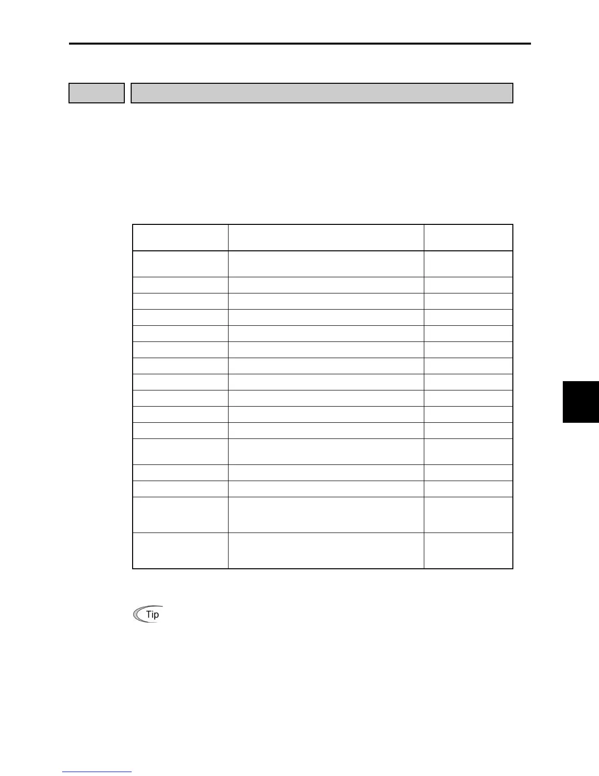
Data for E01 to E03,
E98 and E99
Terminal command assigned
Command symbols
(Input signals)
0, 1, 2
(1000, 1001, 1002)
Select multistep frequency (0 to 7 steps)
(SS1), (SS2) and
(SS4)
4 (1004) Select ACC/DEC time (RT1)
6 (1006) Enable 3-wire operation (2 steps) (HLD)
7 (1007) Coarse to a stop (BX)
8 (1008) Reset alarm (RST)
9 (1009) Enable external alarm trip (THR)
10 (1010) Ready for jogging (JOG)
11 (1011) Switch frequency command 2/1 (Hz2/Hz1)
19 (1019) Enable write from keypad (WE-KP)
20 (1020) Cancel PID control (Hz/PID)
21 (1021) Switch normal/inverse operation (IVS)
24 (1024) Enable communications link
(RS-485 communication, option)
(LE)
33 (1033) Reset PID integral and differential components (PID-RST)
34 (1034) Hold PID integral component (PID-HLD)
98*
Run forward. Short-circuiting terminals
[FWD] and [CM] runs the motor forward.
Opening them decelerates the motor to stop
(FWD)
99*
Run reverse. Short-circuiting terminals [REV]
and [CM] runs the motor reverse. Opening
them decelerates the motor to stop
(REV)
* No negative logic input is allowed for data 98 and 99. Note that negative logic input can never be used for
the motor drive commands (FWD) and (REV).
(Example using negative logic system)
Assigning multistep frequency 2 (SS2) to terminal [X1]
If function code E01 is set to 1, logic is normal ("Active ON"). Short-circuiting
terminals [X1] and [CM] makes (SS2) active.
If E01 is set to 1001, logic is negative ("Active OFF"). Opening the circuit between
[X1] and [CM] makes (SS2) active.
 Loading...


