8.4 Terminal Specifications
8-23
Chap. 8 SPECIFICATIONS
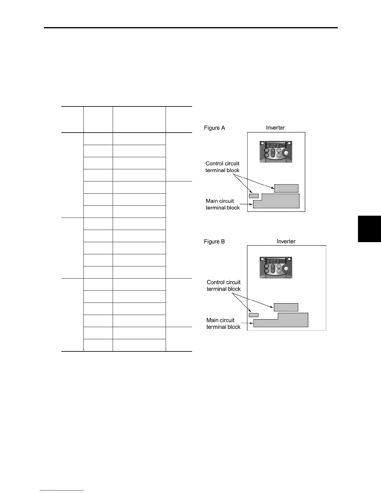
8.4.2 Terminal block arrangement
The terminal blocks shows below. They differ according to the power supply voltage and the applicable
motor rating.
For details about terminal arrangement, refer to Section 8.4.3, "Terminal arrangement diagram and
screw specifications."
Power
supply
voltage
Applicable
motor
rating (HP)
Inverter type Refer to
1/8 FRNF12C1
-2U
1/4 FRNF25C1
-2U
1/2 FRNF50C1
-2U
1 FRN001C1
-2U
Figure A
2 FRN002C1
-2U
3 FRN003C1
-2U
Three-
phase
230 V
5 FRN005C1
-2U
1/2 FRNF50C1
-4U
1 FRN001C1
-4U
2 FRN002C1
-4U
3 FRN003C1
-4U
Three-
phase
460 V
5 FRN005C1
-4U
Figure B
1/8 FRNF12C1
-7U
1/4 FRNF25C1
-7U
1/2 FRNF50C1
-7U
1 FRN001C1
-7U
Figure A
2 FRN002C1
-7U
Single-
phase
230 V
3 FRN003C1
-7U
Figure B
Notes 1) A box (
) in the above table replaces S or E depending on enclosure.
 Loading...


