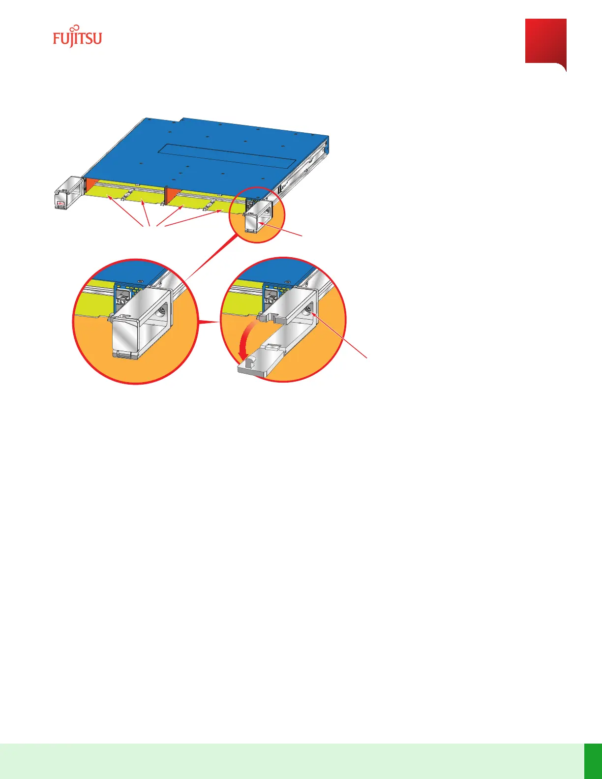
Fiber Restraint
Gate
Open
Closed
PIU Slots
Set Screw
FNC000054_Rev_01
Figure 156
Unlatching Fiber Restraint Gate
Step 32
Aer opening the ber restraint gates, secure the blade to the rack using the set screws on the le- and right-
hand sides of the blade.
Note: The set screws for securing the blade are accessible aer opening the ber restraint gates on the le-
and right-hand sides of the blade.
Step 33
Replace the ber-opc and RJ-45 cables that are previously removed.
Note: Do not plug in the interconnect LCN SFP modules.
Step 34
Verify that power is turned o at the source and install the power cables.
Step 35
Apply power to the tributary blade.
Step Result:
The tributary blade is in shelf provisioning mode and same release as the Main blade.
System Maintenance
Equipment Replacement
401
Release 19.1.1 · Issue 1.1, May 2021
Fujitsu and Fujitsu Customer Use Only
 Loading...