CHAPTER 6: SETPOINTS S2 SYSTEM SETUP
350 FEEDER PROTECTION SYSTEM – INSTRUCTION MANUAL 6–49
S2 System Setup
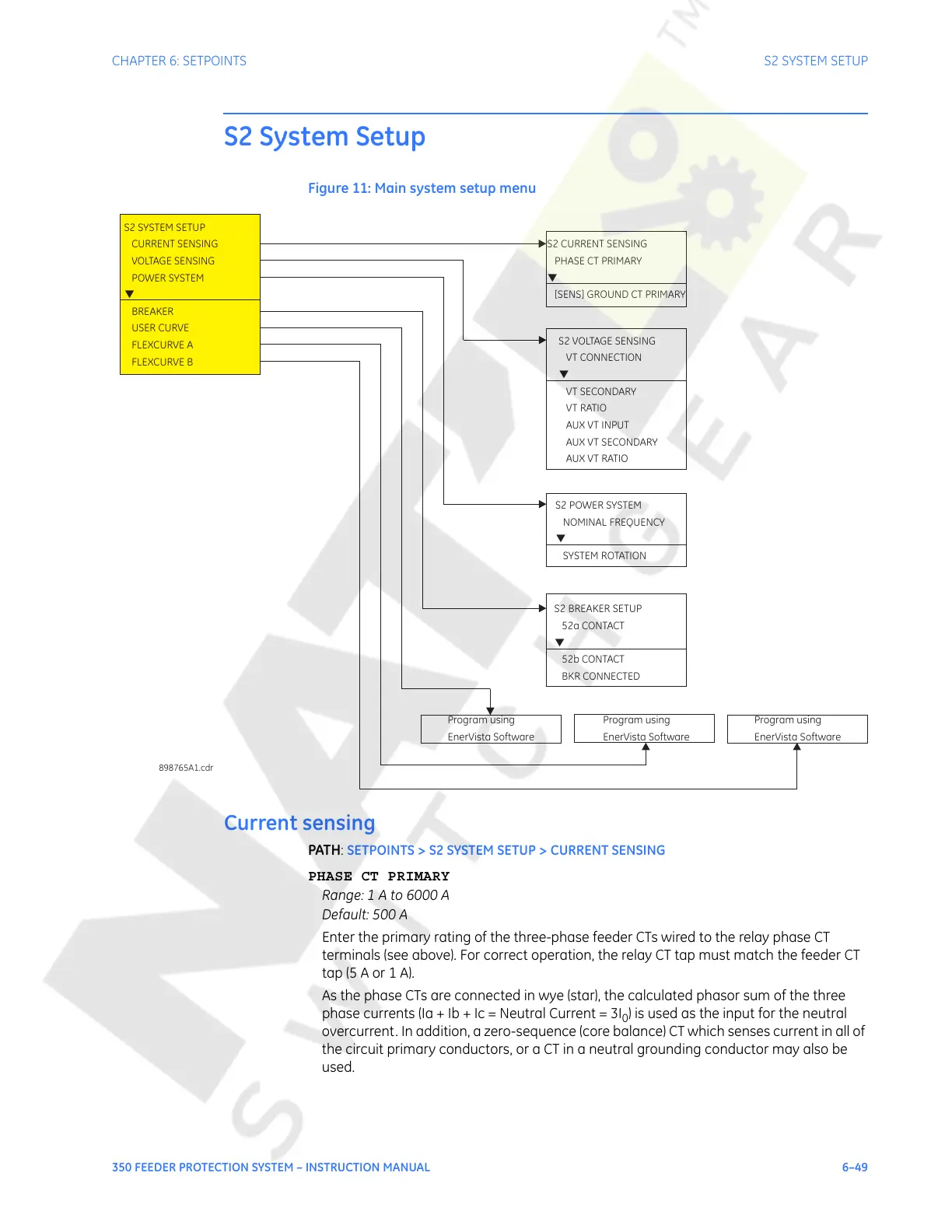
Figure 11: Main system setup menu
Current sensing
PATH: SETPOINTS > S2 SYSTEM SETUP > CURRENT SENSING
PHASE CT PRIMARY
Range: 1 A to 6000 A
Default: 500 A
Enter the primary rating of the three-phase feeder CTs wired to the relay phase CT
terminals (see above). For correct operation, the relay CT tap must match the feeder CT
tap (5 A or 1 A).
As the phase CTs are connected in wye (star), the calculated phasor sum of the three
phase currents (Ia + Ib + Ic = Neutral Current = 3I
0
) is used as the input for the neutral
overcurrent. In addition, a zero-sequence (core balance) CT which senses current in all of
the circuit primary conductors, or a CT in a neutral grounding conductor may also be
used.
Program using
EnerVista Software
S2 CURRENT SENSING
PHASE CT PRIMARY
[SENS] GROUND CT PRIMARY
▼
S2 SYSTEM SETUP
CURRENT SENSING
VOLTAGE SENSING
POWER SYSTEM
BREAKER
USER CURVE
FLEXCURVE A
FLEXCURVE B
▼
898765A1.cdr
S2 VOLTAGE SENSING
VT CONNECTION
VT RATIO
VT SECONDARY
AUX VT INPUT
AUX VT SECONDARY
AUXVTRATIO
▼
S2 BREAKER SETUP
52b CONTACT
52a CONTACT
BKR CONNECTED
▼
S2 POWER SYSTEM
SYSTEM ROTATION
NOMINAL FREQUENCY
▼
Program using
EnerVista Software
Program using
EnerVista Software
Courtesy of NationalSwitchgear.com
 Loading...


