2–10 350 FEEDER PROTECTION SYSTEM – INSTRUCTION MANUAL
ELECTRICAL INSTALLATION CHAPTER 2: INSTALLATION
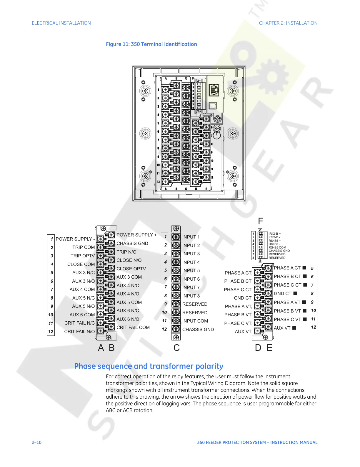
Figure 11: 350 Terminal Identification
Phase sequence and transformer polarity
For correct operation of the relay features, the user must follow the instrument
transformer polarities, shown in the Typical Wiring Diagram. Note the solid square
markings shown with all instrument transformer connections. When the connections
adhere to this drawing, the arrow shows the direction of power flow for positive watts and
the positive direction of lagging vars. The phase sequence is user programmable for either
ABC or ACB rotation.
INPUT 1
INPUT 2
INPUT 3
INPUT 4
INPUT 5
INPUT 6
INPUT 7
INPUT 8
RESERVED
RESERVED
INPUT COM
CHASSIS GND
PHASE A CT
PHASE B CT
PHASE C CT
GND CT
PHASE A VT
PHASE B VT
PHASE C VT
AUX VT
PHASE A CT
PHASE B CT
PHASE C CT
GND CT
PHASE A VT
PHASE B VT
PHASE C VT
AUX VT
■
■
■
■
■
■
■
■
IRIG-B +
IRIG-B -
RS485 +
RS485 -
RS485 COM
CHASSIS GND
RESERVED
RESERVED
POWER SUPPLY +
CHASSIS GND
TRIP N/O
CLOSE N/O
CLOSE OPTV
AUX 3 COM
AUX 4 N/C
AUX 4 N/O
AUX 5 COM
AUX 6 N/C
AUX 6 N/O
CRIT FAIL COM
POWER SUPPLY -
TRIP COM
TRIP OPTV
CLOSE COM
AUX 3 N/C
AUX 3 N/O
AUX 4 COM
AUX 5 N/C
AUX 5 N/O
AUX 6 COM
CRIT FAIL N/C
CRIT FAIL N/O
1
2
3
4
5
6
7
8
9
10
11
12
1
2
3
4
5
6
7
8
9
10
11
12
5
6
7
8
9
10
11
12
AB C DE
F
1
2
3
4
5
6
7
8
Courtesy of NationalSwitchgear.com
 Loading...


