7–6 350 FEEDER PROTECTION SYSTEM – INSTRUCTION MANUAL
M3 BREAKER MAINTENANCE CHAPTER 7: MAINTENANCE
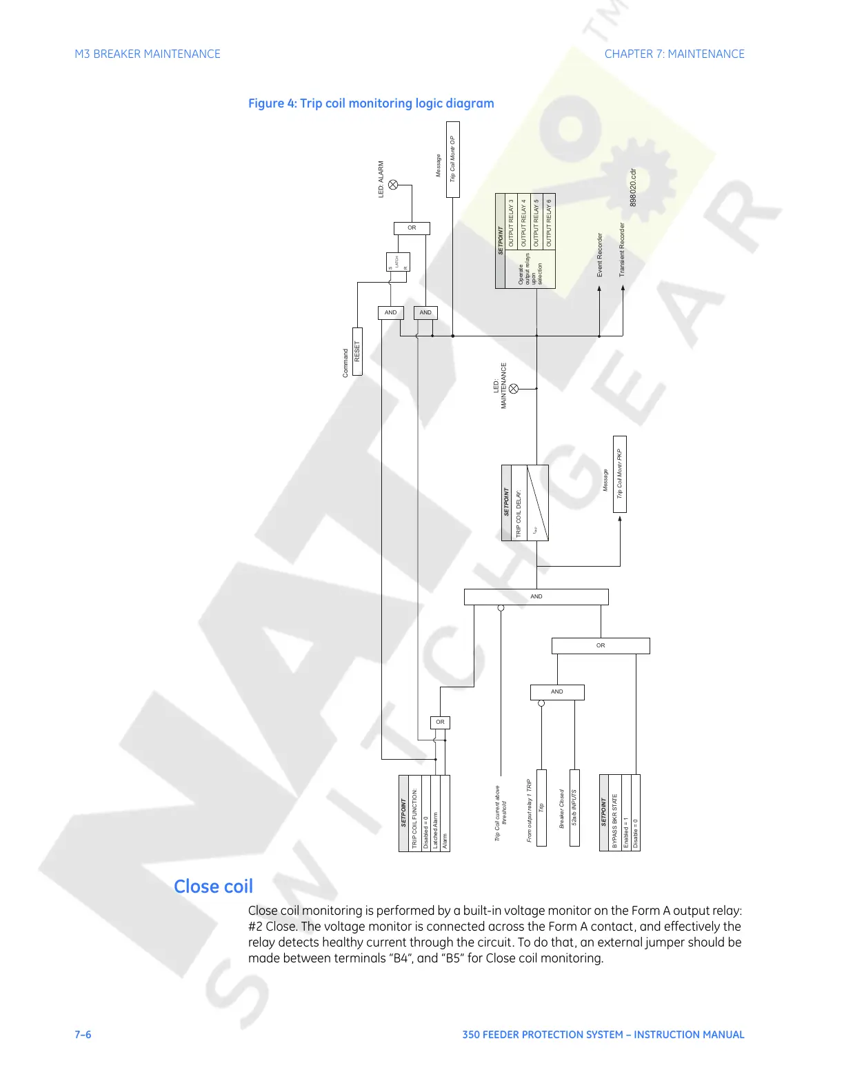
Figure 4: Trip coil monitoring logic diagram
Close coil
Close coil monitoring is performed by a built-in voltage monitor on the Form A output relay:
#2 Close. The voltage monitor is connected across the Form A contact, and effectively the
relay detects healthy current through the circuit. To do that, an external jumper should be
made between terminals “B4”, and “B5” for Close coil monitoring.
SETPOINT
TRIP COIL FUNCTION:
Disabled = 0
Latched Alarm
Event Recorder
Transient Recorder
Alarm
OR
OR
AND
SETPOINT
Operate
output relays
upon
selection
OUTPUT RELAY 4
OUTPUT RELAY 5
OUTPUT RELAY 6
OUTPUT RELAY 3
Trip Coil Montr OP
Message
Trip Coil current above
threshold
AND
OR
52a/b INPUTS
Breaker Closed
Trip
From output relay 1 TRIP
SETPOINT
BYPASS BKR STATE
Enabled = 1
Disable = 0
AND
TRIP COIL DELAY:
SETPOINT
t
PKP
LED:
MAINTENANCE
Trip Coil Montr PKP
Message
LED: ALARM
RESET
Command
AND
S
R
LATCH
898020.cdr
Courtesy of NationalSwitchgear.com
 Loading...


