2–14 350 FEEDER PROTECTION SYSTEM – INSTRUCTION MANUAL
ELECTRICAL INSTALLATION CHAPTER 2: INSTALLATION
NOTE:
An external switch, circuit breaker, or other protective device must be connected near to
the equipment.
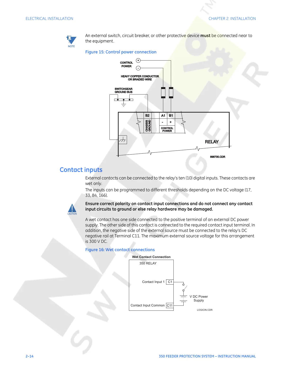
Figure 15: Control power connection
Contact inputs
External contacts can be connected to the relay’s ten (10) digital inputs. These contacts are
wet only.
The inputs can be programmed to different thresholds depending on the DC voltage (17,
33, 84, 166).
CAUTION:
Ensure correct polarity on contact input connections and do not connect any contact
input circuits to ground or else relay hardware may be damaged.
A wet contact has one side connected to the positive terminal of an external DC power
supply. The other side of this contact is connected to the required contact input terminal. In
addition, the negative side of the external source must be connected to the relay’s DC
negative rail at Terminal C11. The maximum external source voltage for this arrangement
is 300 V DC.
Figure 16: Wet contact connections
PPOWER
OR BRAIDED WIRE
OR BRAIDED WIRE
HEAVY COPPER CONDUCTORHEAVY COPPER CONDUCTOR
GROUND BUSGROUND BUS
SWITCHGEAR
-
+
GROUND
B2
A1
B1
+-
CHASSIS
RELAY
CONTROL
898735.CDR898735.CDR
CONTROL
POWER
Wet Contact Connection
350 RELAY
C1Contact Input 1
Contact Input Common
C11
V DC Power
Supply
LOGICIN.CDR
Courtesy of NationalSwitchgear.com
 Loading...


