CHAPTER 2: INSTALLATION ELECTRICAL INSTALLATION
350 FEEDER PROTECTION SYSTEM – INSTRUCTION MANUAL 2–13
Voltage inputs
The 350 relay has four channels for AC voltage inputs, each with an isolating transformer.
Voltage transformers up to a maximum 5000:1 ratio may be used. The nominal secondary
voltage must be in the 50 to 240 V range.The three phase inputs are designated as the “bus
voltage”. The Bus VT connections most commonly used, wye and delta (or open delta), are
shown in the typical wiring diagram.
NOTE:
If Delta VTs are used, the zero sequence voltage (V0) and neutral/sensitive ground
polarizing voltage (–V0) will be zero. Also, with the Delta VT connection, the phase-neutral
voltage cannot be measured and will not be displayed.
NOTE:
The 350 relay can be applied to both metering and protection feeders with up to 65 kV
phase-to-phase voltage. Please ensure that the selected VT ratio and VT secondary do not
result in a primary voltage exceeding 65 kV.
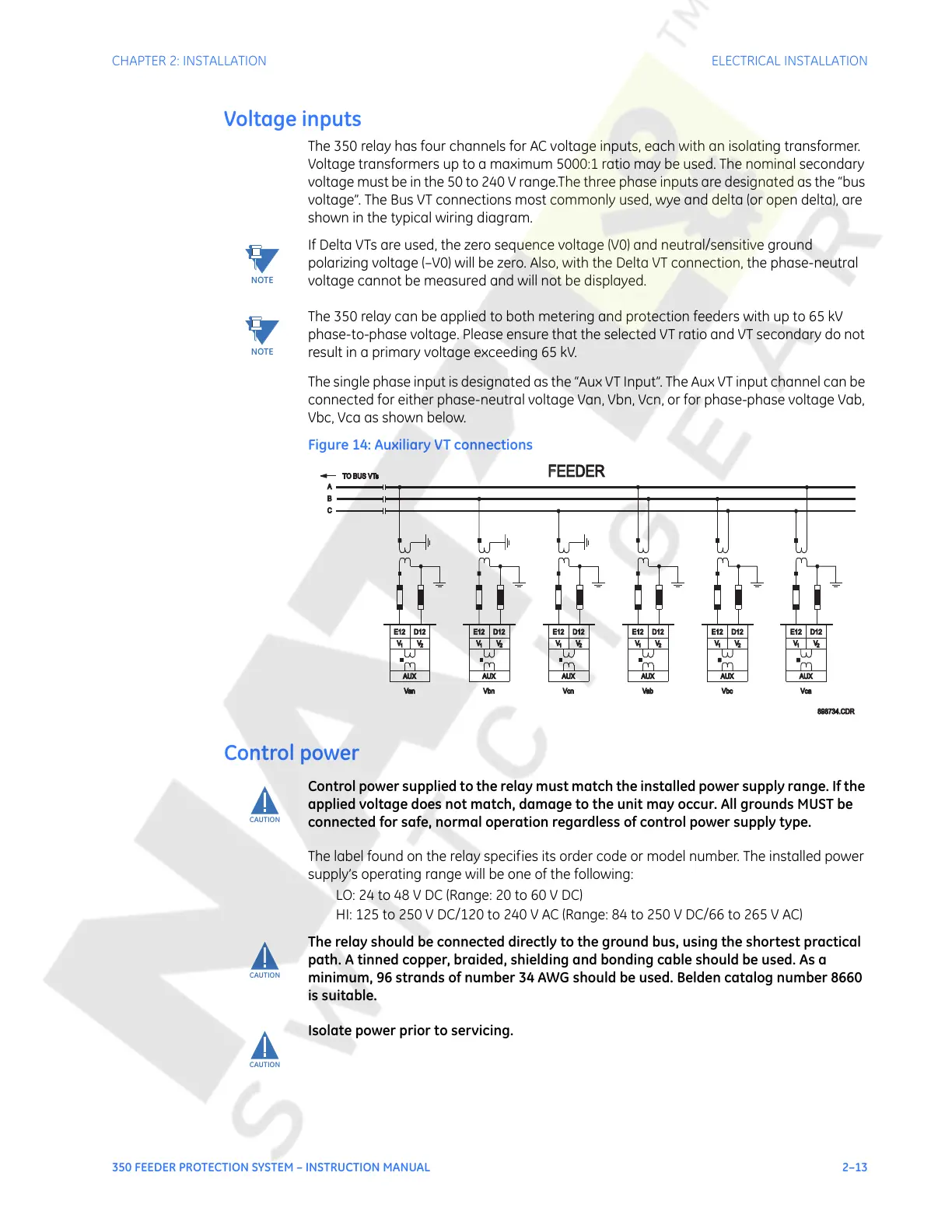
The single phase input is designated as the “Aux VT Input”. The Aux VT input channel can be
connected for either phase-neutral voltage Van, Vbn, Vcn, or for phase-phase voltage Vab,
Vbc, Vca as shown below.
Figure 14: Auxiliary VT connections
Control power
CAUTION:
Control power supplied to the relay must match the installed power supply range. If the
applied voltage does not match, damage to the unit may occur. All grounds MUST be
connected for safe, normal operation regardless of control power supply type.
The label found on the relay specifies its order code or model number. The installed power
supply’s operating range will be one of the following:
LO: 24 to 48 V DC (Range: 20 to 60 V DC)
HI: 125 to 250 V DC/120 to 240 V AC (Range: 84 to 250 V DC/66 to 265 V AC)
CAUTION:
The relay should be connected directly to the ground bus, using the shortest practical
path. A tinned copper, braided, shielding and bonding cable should be used. As a
minimum, 96 strands of number 34 AWG should be used. Belden catalog number 8660
is suitable.
CAUTION:
Isolate power prior to servicing.
FFEEDER
TO BUS VTsTO BUS VTs
A
C
B
E12
AUX
D12
VV
1 2
V
E12
1
V
2
AUX
D12
2
V
1
V
AUX
E12 D12
2
V
1
V
AUX
E12 D12
V
1
V
2
AUX
E12 D12
Van Vbn Vcn Vab Vbc
898734.CDR
V
1
V
2
AUX
E12 D12
Vca
Courtesy of NationalSwitchgear.com
 Loading...


