6–100 350 FEEDER PROTECTION SYSTEM – INSTRUCTION MANUAL
S3 PROTECTION CHAPTER 6: SETPOINTS
Auxiliary
undervoltage
The relay has one Auxiliary Undervoltage element per setpoint group. The input for this
element is the voltage from the auxiliary VT relay terminals, where a single voltage from
the line is connected. The time delay characteristic can be programmed as either definite
time or inverse time. A minimum operating voltage level is programmable to prevent
undesired operation before voltage becomes available.
• Undervoltage Protection: For voltage sensitive loads, such as induction motors, a
drop in voltage will result in an increase in the drawn current, which may cause
dangerous overheating in the motor. The undervoltage protection feature can be used
to either cause a trip or generate an alarm when the voltage drops below a specified
voltage setting for a specified time delay.
• Permissive Functions: The undervoltage feature may be used to block the functioning
of external devices by operating an output relay, when the voltage falls below the
specified voltage setting. Note that all internal features that are inhibited by an
undervoltage condition, such as underfrequency and overfrequency, have their own
inhibit functions independent of the undervoltage protection features.
• Source Transfer Schemes: In the event of an undervoltage, a transfer signal may be
generated to transfer a load from its normal source to a standby or emergency power
source.
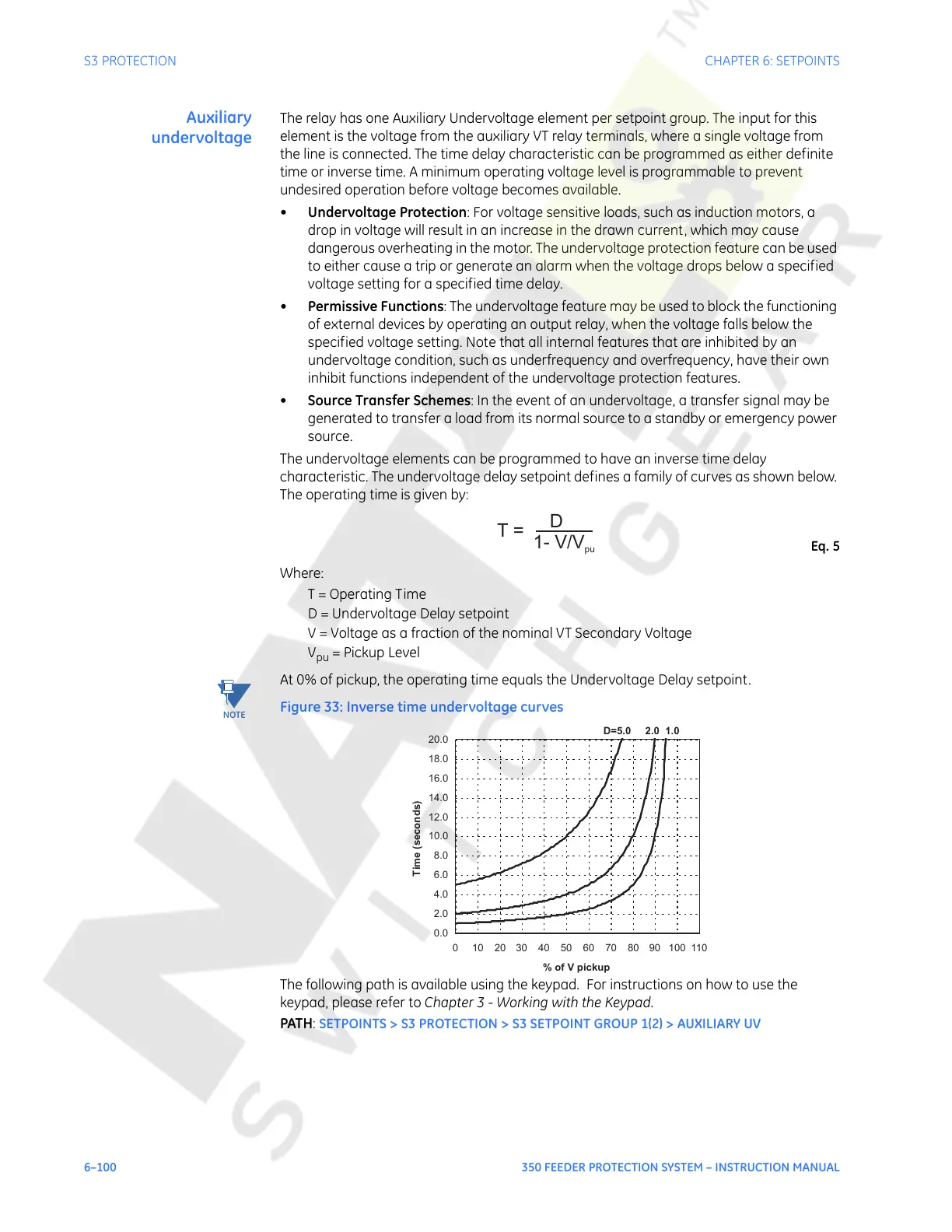
The undervoltage elements can be programmed to have an inverse time delay
characteristic. The undervoltage delay setpoint defines a family of curves as shown below.
The operating time is given by:
Eq. 5
Where:
T = Operating Time
D = Undervoltage Delay setpoint
V = Voltage as a fraction of the nominal VT Secondary Voltage
V
pu
= Pickup Level
NOTE:
At 0% of pickup, the operating time equals the Undervoltage Delay setpoint.
Figure 33: Inverse time undervoltage curves
The following path is available using the keypad. For instructions on how to use the
keypad, please refer to Chapter 3 - Working with the Keypad.
PATH:
SETPOINTS > S3 PROTECTION > S3 SETPOINT GROUP 1(2) > AUXILIARY UV
D=5.0 2.0 1.0
0.0
2.0
4.0
6.0
8.0
10.0
12.0
14.0
16.0
18.0
20.0
0 102030405060708090100110
% of V pickup
Time (seconds)
Courtesy of NationalSwitchgear.com
 Loading...


