3–2 350 FEEDER PROTECTION SYSTEM – INSTRUCTION MANUAL
FRONT CONTROL PANEL INTERFACE CHAPTER 3: INTERFACES
Front control panel interface
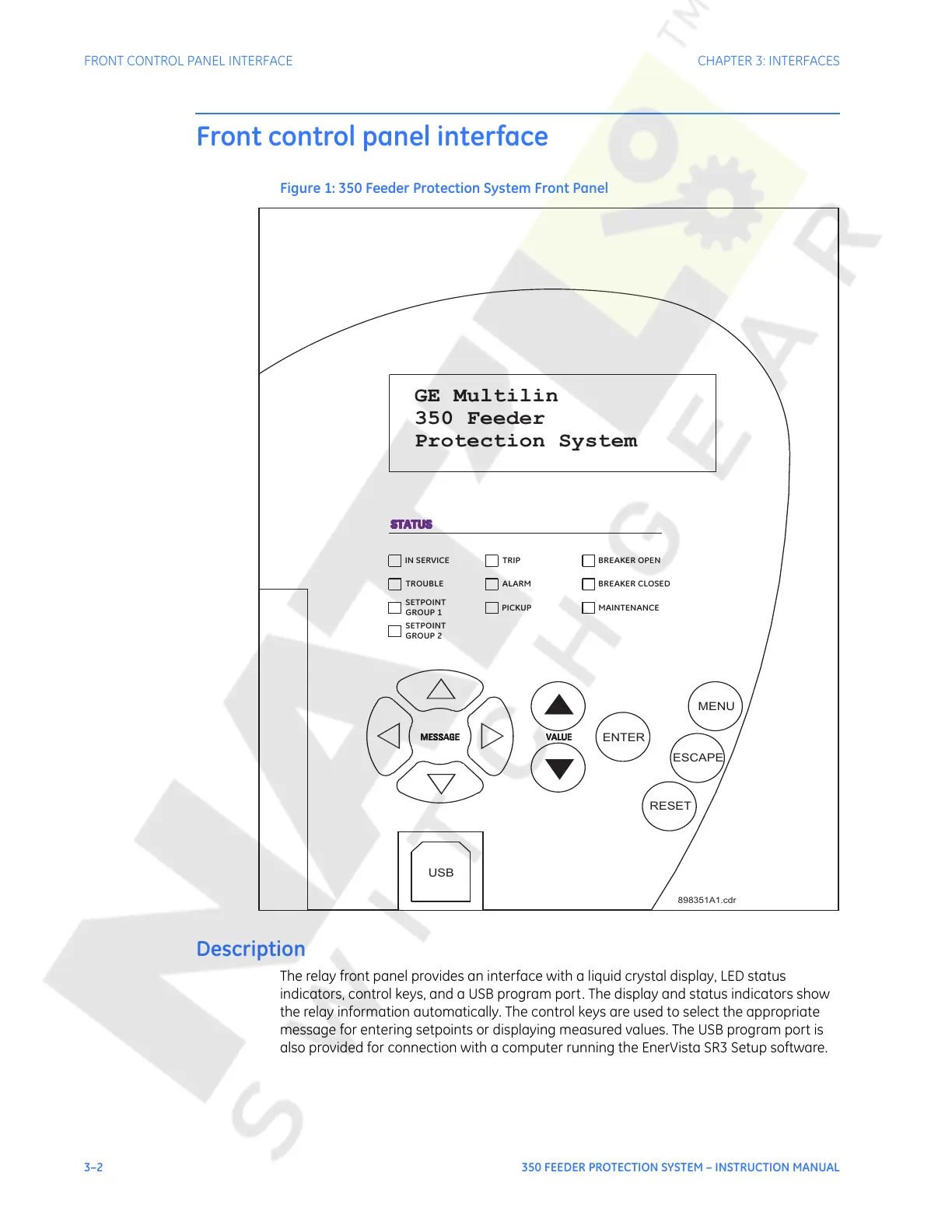
Figure 1: 350 Feeder Protection System Front Panel
Description
The relay front panel provides an interface with a liquid crystal display, LED status
indicators, control keys, and a USB program port. The display and status indicators show
the relay information automatically. The control keys are used to select the appropriate
message for entering setpoints or displaying measured values. The USB program port is
also provided for connection with a computer running the EnerVista SR3 Setup software.
▽
△
◁▷
▲
▼
ENTER
MENU
ESCAPE
RESET
898351A1.cdr
USB
GE Multilin
350 Feeder
Protection System
IN SERVICE
TROUBLE
SETPOINT
GROUP 1
SETPOINT
GROUP 2
TRIP
ALARM
PICKUP
BREAKER OPEN
BREAKER CLOSED
MAINTENANCE
Courtesy of NationalSwitchgear.com
 Loading...


