CHAPTER 6: SETPOINTS S3 PROTECTION
350 FEEDER PROTECTION SYSTEM – INSTRUCTION MANUAL 6–73
Ground directional The Ground Directional element is used to discriminate whether a fault occurs in a forward
or in a reverse direction, and it can be used either individually or as a part of the Ground
Time, or Instantaneous over-current elements. (See the setup for Ground TOC, and Ground
IOC elements.)
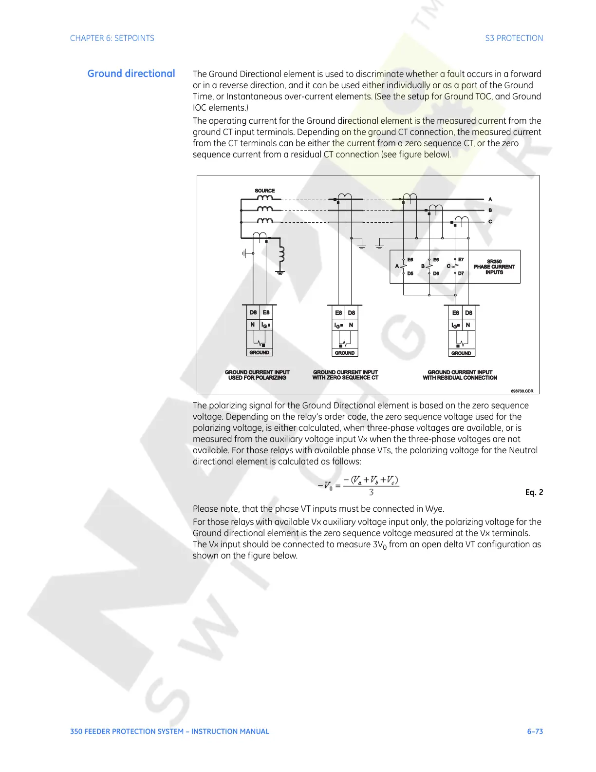
The operating current for the Ground directional element is the measured current from the
ground CT input terminals. Depending on the ground CT connection, the measured current
from the CT terminals can be either the current from a zero sequence CT, or the zero
sequence current from a residual CT connection (see figure below).
The polarizing signal for the Ground Directional element is based on the zero sequence
voltage. Depending on the relay’s order code, the zero sequence voltage used for the
polarizing voltage, is either calculated, when three-phase voltages are available, or is
measured from the auxiliary voltage input Vx when the three-phase voltages are not
available. For those relays with available phase VTs, the polarizing voltage for the Neutral
directional element is calculated as follows:
Eq. 2
Please note, that the phase VT inputs must be connected in Wye.
For those relays with available Vx auxiliary voltage input only, the polarizing voltage for the
Ground directional element is the zero sequence voltage measured at the Vx terminals.
The Vx input should be connected to measure 3V
0
from an open delta VT configuration as
shown on the figure below.
SOURCE
898730.CDR898730.CDR
A
B
C
USED FOR POLARIZINGUSED FOR POLARIZING
GROUND CURRENT INPUTGROUND CURRENT INPUT
SR350
PHASE CURRENT
PHASE CURRENT
INPUTS
A B C
GROUND CURRENT INPUTGROUND CURRENT INPUT
WITH ZERO SEQUENCE CTWITH ZERO SEQUENCE CT
GROUND CURRENT INPUTGROUND CURRENT INPUT
WITH RESIDUAL CONNECTIONWITH RESIDUAL CONNECTION
E8 D8
G
GROUND
I N NI
G
E5
D5
D6
E6
D7
E7
G
IN
GROUND
D8 E8
GROUND
D8E8
Courtesy of NationalSwitchgear.com
 Loading...


