6–118 350 FEEDER PROTECTION SYSTEM – INSTRUCTION MANUAL
S4 CONTROLS CHAPTER 6: SETPOINTS
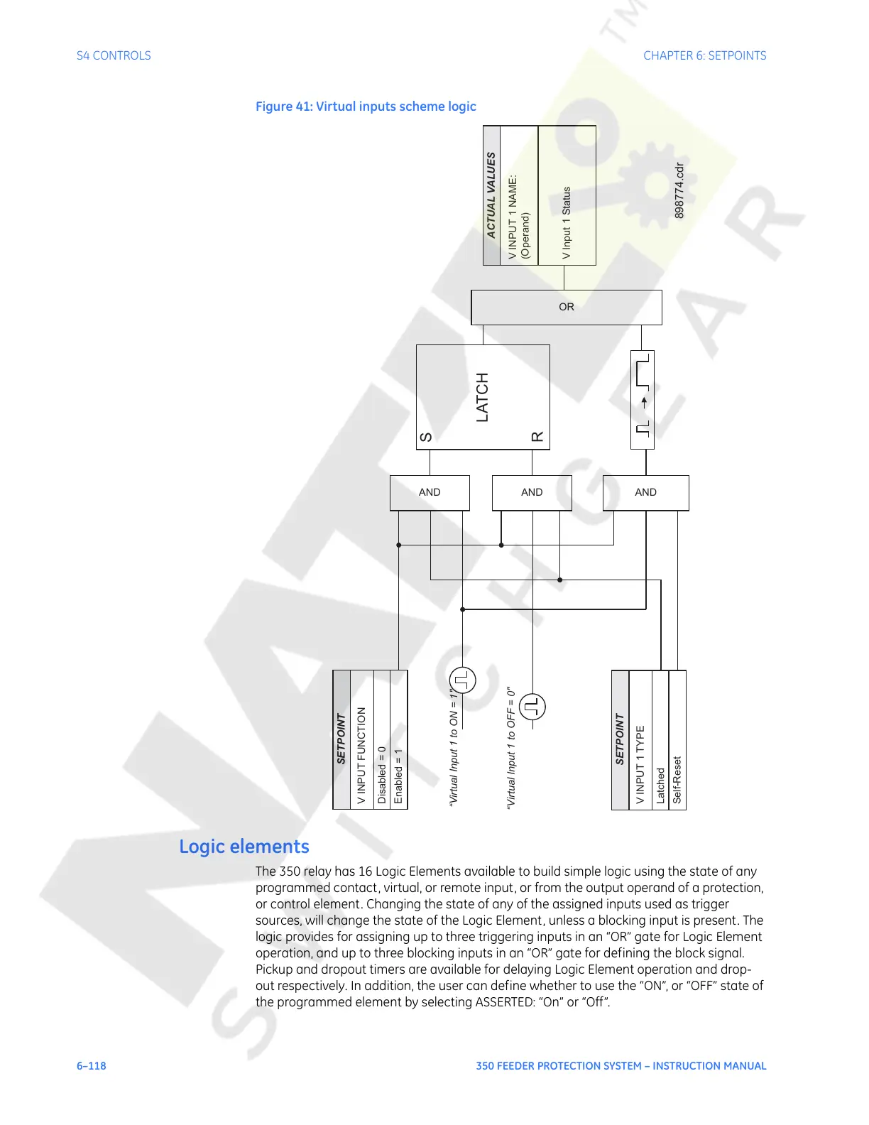
Figure 41: Virtual inputs scheme logic
Logic elements
The 350 relay has 16 Logic Elements available to build simple logic using the state of any
programmed contact, virtual, or remote input, or from the output operand of a protection,
or control element. Changing the state of any of the assigned inputs used as trigger
sources, will change the state of the Logic Element, unless a blocking input is present. The
logic provides for assigning up to three triggering inputs in an “OR” gate for Logic Element
operation, and up to three blocking inputs in an “OR” gate for defining the block signal.
Pickup and dropout timers are available for delaying Logic Element operation and drop-
out respectively. In addition, the user can define whether to use the “ON”, or “OFF” state of
the programmed element by selecting ASSERTED: “On” or “Off”.
SETPOINT
V INPUT FUNCTION
Disabled = 0
Enabled =1
AND
SETPOINT
V INPUT 1 TYPE
Latched
Self-Reset
AND
AND
“Virtual Input 1 toON=1"
“Virtual Input 1 to OFF = 0"
S
R
LATCH
OR
ACTUAL VALUES
V INPUT
1 NAME:
(Operand)
VInput1Status
898774.cdr
Courtesy of NationalSwitchgear.com
 Loading...


