2–12 350 FEEDER PROTECTION SYSTEM – INSTRUCTION MANUAL
ELECTRICAL INSTALLATION CHAPTER 2: INSTALLATION
Figure 12: Ground/Sensitive Ground wiring
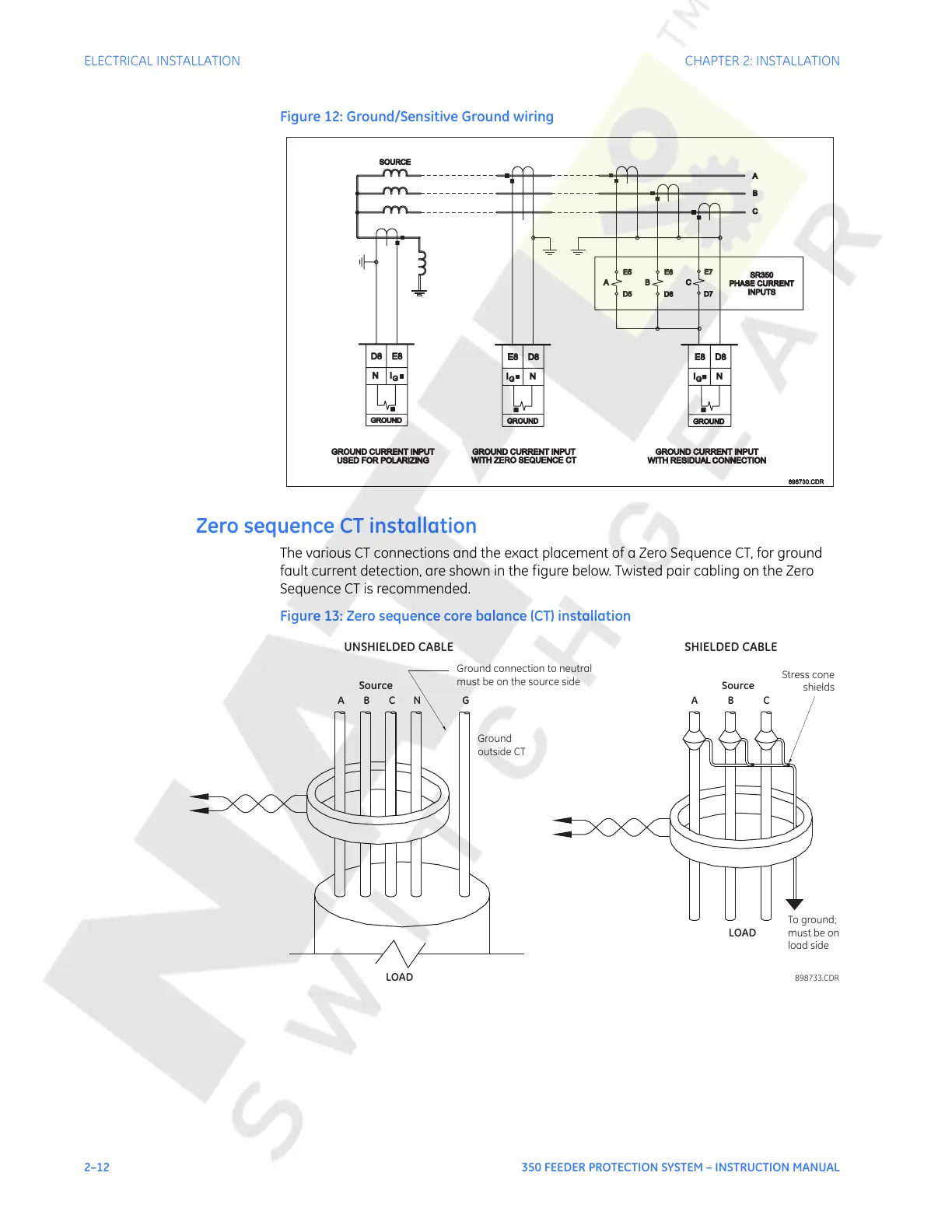
Zero sequence CT installation
The various CT connections and the exact placement of a Zero Sequence CT, for ground
fault current detection, are shown in the figure below. Twisted pair cabling on the Zero
Sequence CT is recommended.
Figure 13: Zero sequence core balance (CT) installation
SOURCE
898730.CDR898730.CDR
A
B
C
USED FOR POLARIZINGUSED FOR POLARIZING
GROUND CURRENT INPUTGROUND CURRENT INPUT
SR350
PHASE CURRENT
PHASE CURRENT
INPUTS
A B C
GROUND CURRENT INPUTGROUND CURRENT INPUT
WITH ZERO SEQUENCE CTWITH ZERO SEQUENCE CT
GROUND CURRENT INPUTGROUND CURRENT INPUT
WITH RESIDUAL CONNECTIONWITH RESIDUAL CONNECTION
E8 D8
G
GROUND
I N NI
G
E5
D5
D6
E6
D7
E7
G
IN
GROUND
D8 E8
GROUND
D8E8
Ground connection to neutral
must be on the source side
UNSHIELDED CABLE
LOAD
ABCN G
Ground
outside CT
Source
LOAD
SHIELDED CABLE
898733.CDR
ABC
Source
To ground;
must be on
load side
Stress cone
shields
Courtesy of NationalSwitchgear.com
 Loading...


