2–8 350 FEEDER PROTECTION SYSTEM – INSTRUCTION MANUAL
ELECTRICAL INSTALLATION CHAPTER 2: INSTALLATION
Terminal identification
NOTE
NOTE:
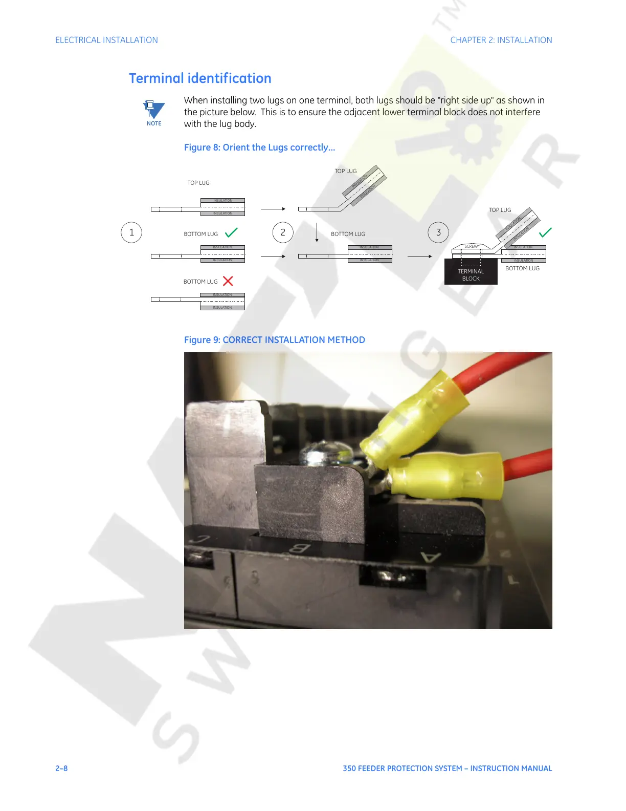
When installing two lugs on one terminal, both lugs should be "right side up" as shown in
the picture below. This is to ensure the adjacent lower terminal block does not interfere
with the lug body.
Figure 8: Orient the Lugs correctly...
Figure 9: CORRECT INSTALLATION METHOD
TOP LUG
BOTTOM LUG
INSULATION
INSULATION
INSULATION
INSULATION
TOP LUG
BOTTOM LUG
INSULATION
INSULATION
INSULATION
INSULATION
TOP LUG
BOTTOM LUG
INSULATION
INSULATION
INSULATION
INSULATION
TERMINAL
BLOCK
SCREW*
12 3
BOTTOM LUG
INSULATION
INSULATION
Courtesy of NationalSwitchgear.com
 Loading...


