CHAPTER 3: INTERFACES FRONT CONTROL PANEL INTERFACE
350 FEEDER PROTECTION SYSTEM – INSTRUCTION MANUAL 3–5
This indicator will light ON upon pickup condition generated by any of the relay
features. The indicator will turn off if no pickup condition is detected.
• BREAKER OPEN: Red/Green – programmable
When the breaker is open, this indicator will be on continuously.
• BREAKER CLOSED: Red/Green – programmable
When the breaker is closed, this indicator will be on continuously.
Breaker status indication is based on the breaker’s 52a and 52b contacts. With both
contacts wired to the relay, closed breaker status is determined by closed 52a contact
and opened 52b contact. Visa-versa the open breaker status is determined by opened
52a contact and closed 52b contact. If both 52a and 52b contacts are open, due to a
breaker being racked out from the switchgear, both the Breaker Open and Breaker
Closed LED Indicators will be off.
NOTE:
It is strongly recommended to detect the breaker status by using both 52a and 52b
contacts.
The 350 provides also detecting the breaker status by using only one contact: either
52a or 52b. However, one should be aware that in such cases, it would be impossible
to distinguish between a breaker open state and breaker racked out state, unless
another contact from the breaker is wired to the relay.
To clarify this ambiguity, the BKR CONNECTED function under SETPOINTS/S2 SYSTEM
SETUP/S2 BREAKER should be programmed to an additional contact input. When this
additional input is closed, a single 52a or 52b contact will show both breaker states.
When the breaker is racked out, this additional breaker connected input should be
open. In this case, both breaker status indicators will be off.
• MAINTENANCE: Amber
This LED may indicate both breaker or relay maintenance depending on the
programmed maintenance elements. The LED will turn on upon operation of a
maintenance element.
Relay messages
Target messages Target messages are automatically displayed for any active condition on the relay such as
pickups, trips, or alarms.
The relay displays the most recent event first, and after 5 seconds will start rolling up the
other target messages until the conditions clear and/or the RESET command is initiated.
The Target Messages can be reviewed by pressing either the MESSAGE UP or MESSAGE
DOWN key. If a RESET command is not performed but any of the other faceplate
pushbuttons is pressed, the display will not show the target messages unless the user
navigates to
ACTUAL VALUES > A4 TARGET MESSAGES, where they can be reviewed. If the
target messages have not been cleared before the user presses a pushbutton different
from “RESET”, they will reappear on the screen after the time specified under the
SETPOINTS > S1 RELAY SETUP > S1 FRONT PANEL > MESSAGE TIMEOUT setting, that will start
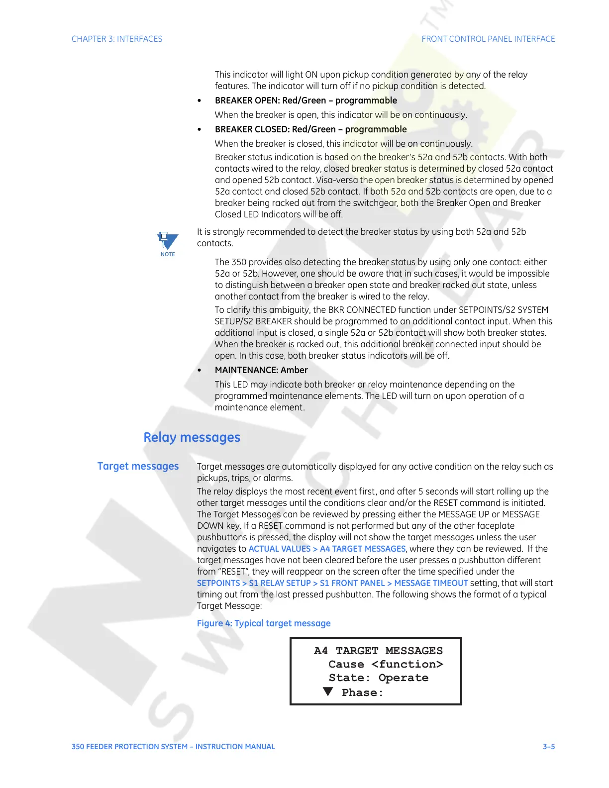
timing out from the last pressed pushbutton. The following shows the format of a typical
Target Message:
Figure 4: Typical target message
A4 TARGET MESSAGES
Cause <function>
State: Operate
Phase:
▼
Courtesy of NationalSwitchgear.com
 Loading...


