Wire size
Terminal
screw size
Model of the round
crimp terminal
Fastening torque
Model of insulating
sleeve
Model of
crimp tool
mm
2
(AWG) kgf.cm (in.lbs)
14 (6)
M4 R14-4 12.2 to 14 (10.4 to 12.1) TIC 14 NH 1 / 9
M5 R14-5 20.4 to 24 (17.7 to 20.8) TIC 14 NH 1 / 9
M6 R14-6 25.5 to 30.0 (22.1 to 26.0) TIC 14 NH 1 / 9
M8 R14-8 61.2 to 66.0 (53.0 to 57.2) TIC 14 NH 1 / 9
22 (4)
M6 R22-6 25.5 to 30.0 (22.1 to 26.0) TIC 22 NOP 60/ 150H
M8 R22-8 61.2 to 66.0 (53.0 to 57.2) TIC 22 NOP 60/ 150H
30 / 38 (3 /2)
M6 R38-6 25.5 to 30.0 (22.1 to 26.0) TIC 38 NOP 60/ 150H
M8 R38-8 61.2 to 66.0 (53.0 to 57.2) TIC 38 NOP 60/ 150H
50 / 60 (1/1/0)
M8 R60-8 61.2 to 66.0 (53.0 to 57.2) TIC 60 NOP 60/ 150H
M10 R60-10 102 to 120 (88.5 to 104) TIC 60 NOP 150H
70 (2/0)
M8 R70-8 61.2 to 66.0 (53.0 to 57.2) TIC 60 NOP 150H
M10 R70-10 102 to 120 (88.5 to 104) TIC 60 NOP 150H
80 (3/0)
M10 R80-10 102 to 120 (88.5 to 104) TIC 80 NOP 150H
M16 R80-16 255 to 280 (221 to 243) TIC 80 NOP 150H
100 (4/0)
M10 R100-10 102 to 120 (88.5 to 104) TIC 100 NOP 150H
M12 R100-12 143 to 157 (124 to 136) TIC 100 NOP 150H
M16 R80-16 255 to 280 (221 to 243) TIC 80 NOP 150H
3.7. Wiring Peripheral Power Devices
• After power is shut off to the inverter the capacitors will slowly discharge. Do NOT touch the inverter circuit
or replace any components until the “CHARGE” indicator is off.
• Do NOT wire or connect/disconnect internal connectors of the inverter when the inverter is powered up or
after power off but the “CHARGE”” indicator is on.
• Do NOT connect inverter output U, V and W to the AC power source. This will result in damage to the
inverter.
• The inverter must be properly grounded. Use terminal E to connect earth ground and comply with local
standards.
• It is required to disconnect the ground wire in the control board if the inverter is not grounded.
• Do NOT perform a dielectric voltage withstand test (Megger) on the inverter this will result in inverter dam-
age to the semiconductor components.
• Do NOT touch any of the components on the inverter control board to prevent damage to the inverter by
static electricity.
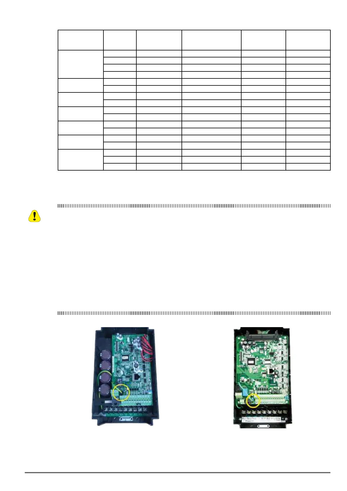
230V Class : 0.75~1.5 kW / 400V Class: 0.75~2.2 kW 230V Class : 2.2~5.5 kW / 400V Class: 3.7~5.5 kW
Disconnect the ground wire of J1. on the control board (C/B). Disconnect the ground wire of J1. on the control board (C/B).
Caution
VDI100 • Instruction manual 21
 Loading...


