8.7. Direct/UnattendedStartup
The unattended startup function prevents the inverter from starting automatically when a run command is pres-
ent at time of power-up. To use USP command set one of the multi-function digital input functions to #50 (USP
Startup).
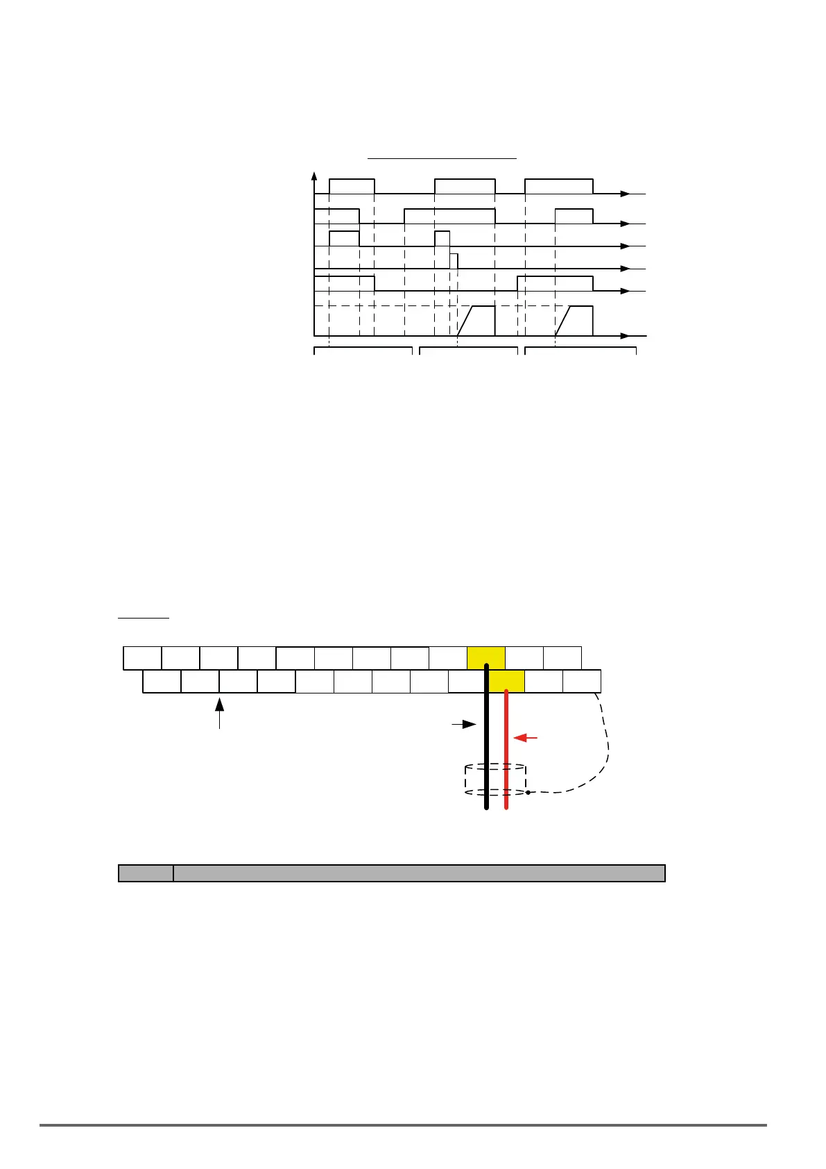
UnattendedStartupProtection
Power Supply
Run Command
Fault (Alarm)
Fault Reset
USP Command
Output Frequency
t
t
t
t
t
t
USP active on power-up.
USP warning clears when
run command is removed.
USP not active, when
fault is reset the inverter
restarts automatically.
When run command is off at
power-up and USP is active
the inverter starts normally.
8.8. Analog Output Setup
Signal: Use parameter 04-11 to select the analog output signal for AO1 and parameter 04-16 to select the
analog output signal for AO2.
Gain: Use parameter 04-12 to adjust the gain for AO1 and parameter 04-17 to adjust the gain for AO2.
Adjust the gain so that the analog output (10V) matches 100% of the selected analog output signal (04-11 for
AO1 and 04-16 for AO2).
Bias: Use parameter 04-13 to adjust the bias for AO1 and parameter 04-18 to adjust the bias for AO2.
Adjust the bias so that the analog output (0V) matches 0% of the selected analog output signal (04-11 for AO1
and 04-16 for AO2).
Example: Analog Output 1 Wiring
E
DO2 24VG S2 S4 S6 S8 24V +12V
GND
AI1 AI2
DO1 DOG S1 S3 S7 F1 F2 PI
AO1
AO2
E
Connect shield
to control
ground terminal
Common/
GND
Control Terminals /
User Terminals
S5
Analog
Output 1
+
-
Code Parameter Name / Range
04-11 AO1 function Setting
0: Output frequency
1: Frequency command
2: Output voltage
3: DC voltage
4: Output current
5: Output power
6: Motor speed
7: Output power factor
8: AI1 input
9: AI2 input
10: Torque command
11: q -axis current
12: d-axis current
13: Speed deviation
14: Reserved
324 VDI100 • Instruction manual
 Loading...


