10. Troubleshooting and Fault Diagnostics
10.1. General
Inverter fault detection and early warning / self-diagnosis function. When the inverter detects a fault, a fault
message is displayed on the keypad. The fault contact output energizes and the motor will coast to stop (The
stop method can be selected for specic faults).
When the inverter detects a warning / self-diagnostics error, the digital operator will display a warning or self-di-
agnostic code, the fault output does not energize in this case. Once the warning is removed, the system will
automatically return to its original state.
10.2. Fault Detection Function
When a fault occurs, please refer to Table 10.2.1 for possible causes and take appropriate measures.
Use one of the following methods to restart:
1. Set one of multi-function digital input terminals (03-00, 03-07) to 17 (Fault reset); activate input
2. Press the reset button on the keypad.
3. Power down inverter wait until keypad goes blank and power-up the inverter again.
When a fault occurs, the fault message is stored in the fault history (see group 12 parameters).
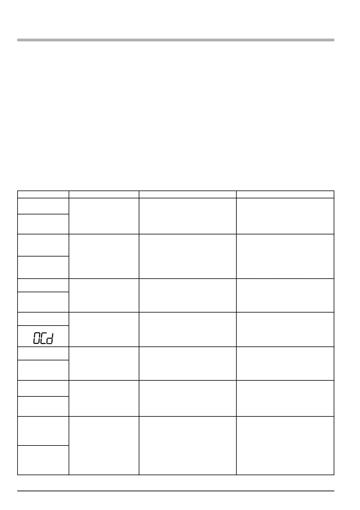
LED display Description Cause Possible solutions
OC
over current
The inverter output current exce-
eds the overcurrent level (200% of
the inverter rated current).
• Acceleration / Deceleration time is too short.
• Contactor at the inverter output side.
• A special motor or applicable
size is greater
than the inverter rated value.
•Short circuit or ground fault.
• Extend acceleration / deceleration time.
• Check the motor wiring.
• Disconnect motor and try running inverter.
OC
OCA
over current
The inverter output current
exceeds the overcurrent level in
acceleration time.
•Acceleration time is too short.
•Size of motor is bigger than inverter.
•Short circuit between winding and shell of
motor.
•Short circuit between wire and ground of
motor.
•IGBT broken module.
•Set the longer acceleration time.
•Change to bigger size of inverter.
•Examine motor.
•Check the wire.
•Replace IGBT module (Please contact Gefran
Technical Assistance).
OCA
OCC
over current
The inverter output current
exceeds the overcurrent level in
constant speed.
•Instantaneous change of load.
•Instantaneous change of current.
•Change to bigger size of inverter.
•Add reactor to power source.
OCC
OCd
over current
The inverter output current
exceeds the overcurrent level in
deceleration time.
•Deceleration time is too short. •Set the longer acceleration time.
SC
short circuit
Inverter output short circuit or
ground fault.
• Short circuit or ground fault (08-23 = 1).
• Motor damaged (insulation).
• Wire damage or deterioration.
• Check the motor wiring.
• Disconnect motor and try running inverter.
SC
GF
Ground fault
The current to ground exceeds
50% of the inverter rated output
current (08-23 = 1, GF function is
enabled).
• Motor damaged (insulation).
• Wire damage or deterioration.
• Inverter DCCT sensors defect.
• Replace motor.
• Check the motor wiring.
• Disconnect motor and try running inverter.
• Check resistance between cables and ground.
• Reduce carrier frequency
GF
OV
Over voltage
DC bus voltage exceeds the OV
detection level:
410Vdc: 230V class
820Vdc: 460V class
(For 440V class, if input voltage
01-14 is set lower than 400V,
the OV detection value will is
decreased to 700Vdc).
• Deceleration time set too short, resulting in
regenerative energy flowing back from motor to
the inverter.
• The inverter input voltage is too high.
• Use of power factor correction capacitors.
• Excessive braking load.
• Braking transistor or resistor defective.
• Speed search parameters set incorrectly.
• Increase deceleration time
• Reduce input voltage to comply with the
input voltage requirements or install an AC line
reactor to lower the input voltage.
• Remove the power factor correction capa-
citor.
• Use dynamic braking unit.
• Replace braking transistor or resistor.
• Adjust speed search parameters.
OU
330 VDI100 • Instruction manual
 Loading...


