Appendix A: Communication Networks
A1.1RS485–Network(Modbus)
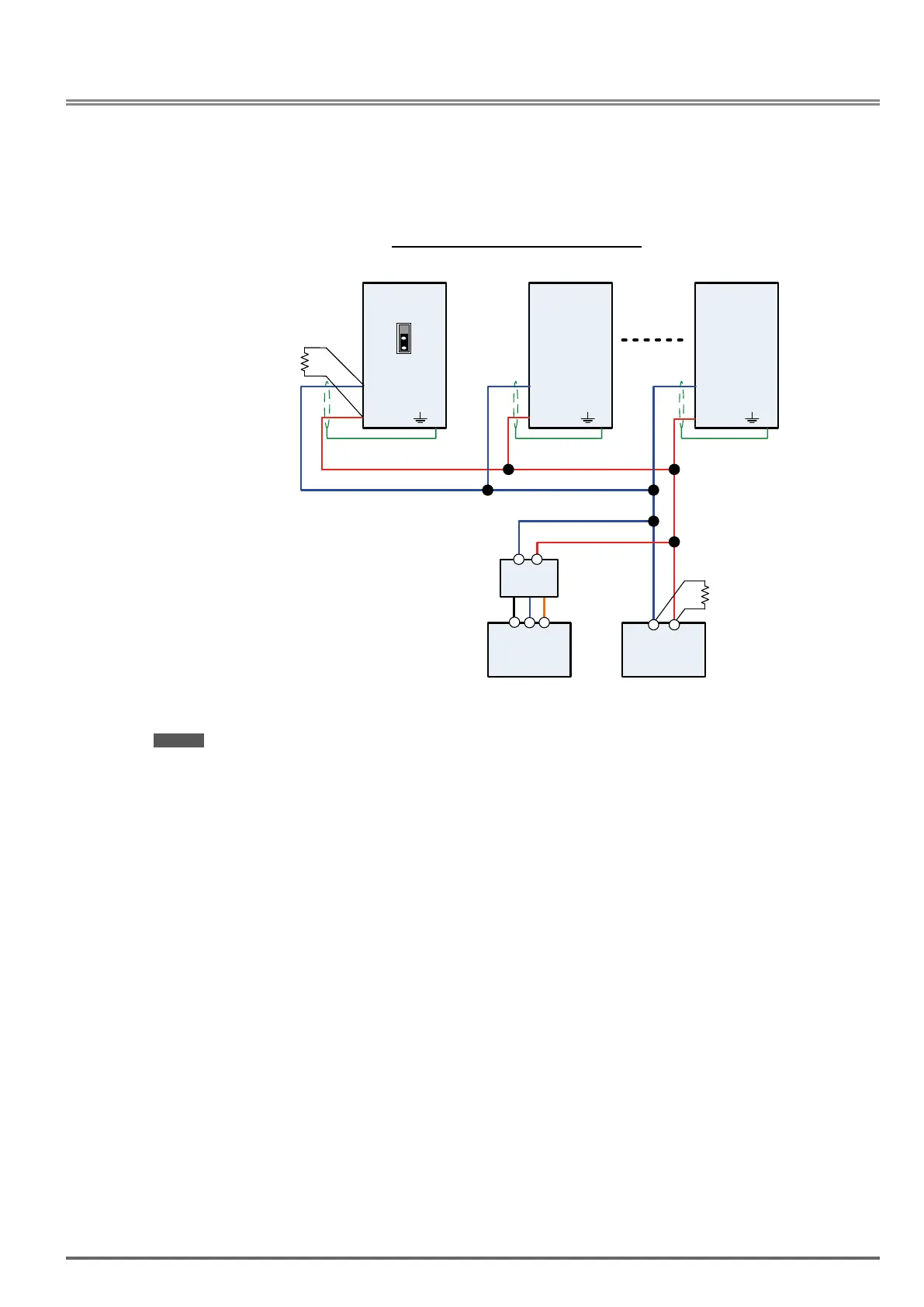
This section shows a RS485 network consisting of several inverters communicating using the built-in Modbus
RTU protocol.
WiringdiagramRS485ModbusRTUNetwork
S-
Inverter #1
S+
S-
Inverter #2
S+
S-
Inverter #n
S+
PC / PLC
RS485
Resistor
120 Ohm
RS232/
RS485
Resistor
120 Ohm
+
-
+
-
E E E
RX
TX
GND
PC / PLC
RS232
SW4
Notes:
- A PC / PLC controller with a built-in RS-485 interface can be connected directly to the RS-485 network. Use
a RS232 to RS485 converter to connect a PC / PLC with a built-in RS-232 interface.
- A maximum of 31 inverters can be connected to the network. Terminating resistors of 120 ohm must be
installed at both end of the network.
Refer to
VDI100 RS-485 Modbus communication manual for more information.
VDI100 • Instruction manual 351
 Loading...


