Code Parameter Name / Range
03-31 Scale of pulse input
Depending on the setting of 03-30
03-30 = 0: 50~32000Hz
03-30 = 1:10~1000Hz
Pulse input scaling, 100% = Maximum pulse frequency.
Code Parameter Name / Range
03-32 Pulse input gain
0.0~1000.0 %
Target value (03-03) in % = Pulse input frequency scaled to 100% based on maximum pulse frequency (O3-31)
times the gain (03-32) + bias (03-33).
Code Parameter Name / Range
03-33 Pulse input bias
-100.0~100.0 %
Target value (03-03) in % = Pulse input frequency scaled to 100% based on maximum pulse frequency (O3-31)
times the gain (03-32) + bias (03-33).
Code Parameter Name / Range
03-34 Pulse input filter time
0.00~2.00 s
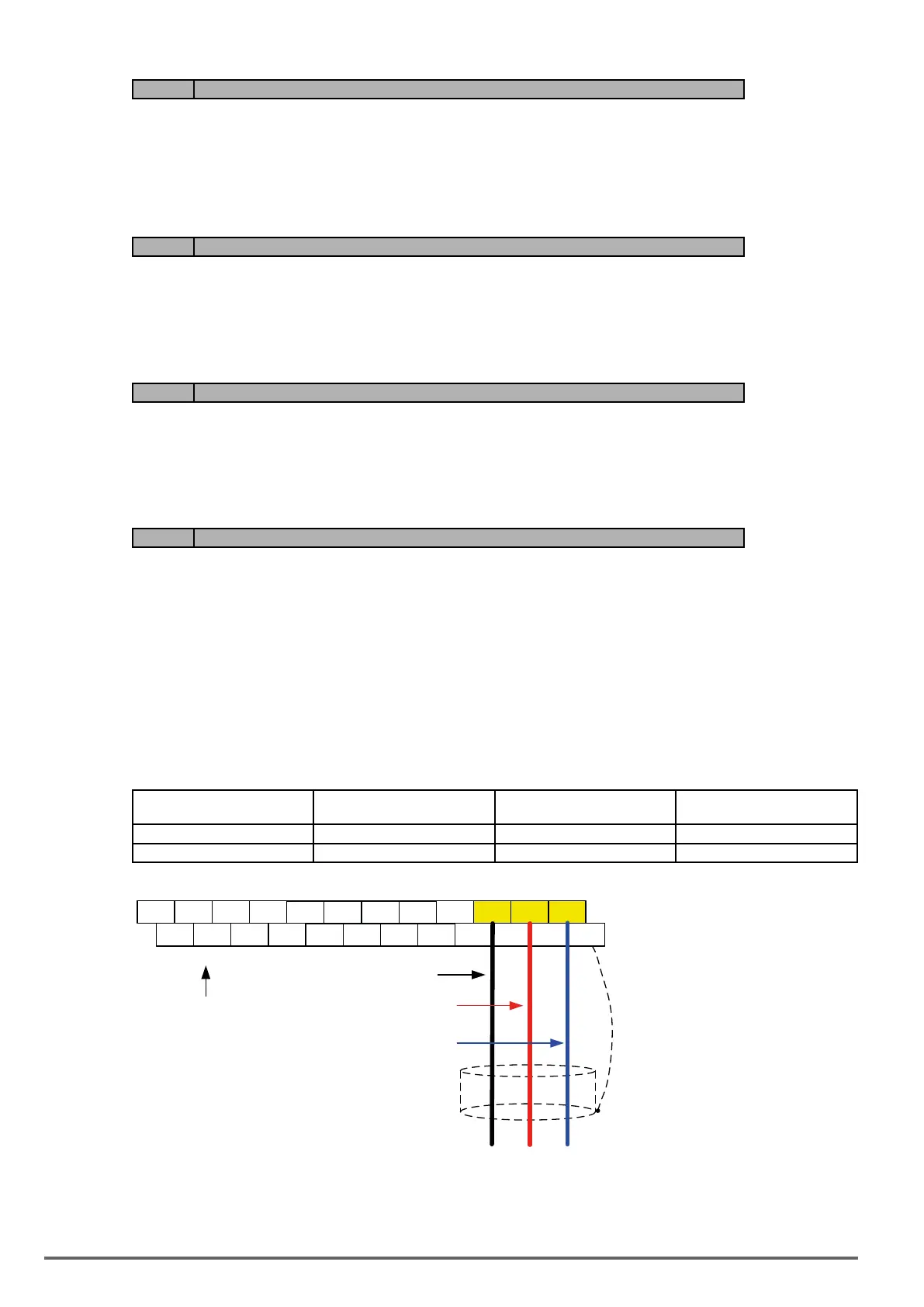
6.5. Reference from two Analog Inputs
Analog input AI1 is used as master frequency reference and analog input AI2 is used as auxiliary frequency
reference.
AnalogReferenceAI1:0–10V(Setting00-05=1)
AnalogReferenceAI2:0–10V(Setting00-06=1,04-05=1)
AI1 – Analog Input 1 AI2 – Analog Input 2 04-00 Setting
(Default = 1)
Dipswitch SW2
(Default ‘V’)
0 ~ 10V 0 ~ 10V 0 Set to ‘V’
0 ~ 10V 4 ~ 20mA 1 Set to ‘I’
E
DO2
24VG
S2 S4 S6 S8 24V +12V GND
AI1 AI2
DO1 DOG S1 S3 S5 S7 F1 F2 PI AO1 AO2
E
Connect shield to
control ground terminal
0 – 10 V
+
-
Analog Input AI1
Common/0V, GND
Control Terminals /
User Terminals
Analog Input AI2
+
314 VDI100 • Instruction manual
 Loading...


