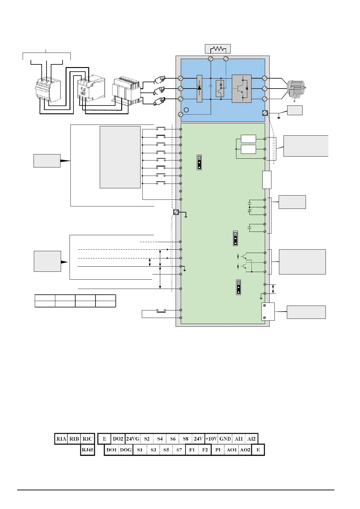
3.8. General Wiring Diagram
L1/R
L2/S
L3/T
U/T1
V/T2
W/T3
B1/P
B2 *1
3ph Induction motor
E
Main Power Section
+10V: Power for Analog Input
(max. 20mA)
AI1: Multi-Function Analog Input
AI2: Multi-Function Analog Input
PI Pulse Input 32kHz Max.
S1
DOG
DO1
Multi-Functional transistor
digital outputs
Open Collector, 48V
@50mA
(opto-isolated)
(R1A)
(R1C)
(R1B)
NC
NO
Multi-Function
Relay Output
External
Analog
Inputs
Digital Input
Section
+
-
Contact rating:
250 VAC < 1.0A
30 VDC < 1.0A
-
Ground
< 100Ω
Analog
Output 1
Analog
Output 2
AO1
AO2
GND
Analog Outputs
AO1 : 0 – 10 VDC
AO2 : 0 – 10 VDC / 4-20mA
DO2
S2
S3
S4
S5
S6
S7
S8
24V Power terminal for digital signal (source)
VDI100
Multi-
Functional
Digital Inputs
External base block
Jog Command
Multi-Step Speed Ref. 3
Fault Reset
Multi-Step Speed Ref. 2
Multi-Step Speed Ref. 1
FWD / STOP
REV / STOP
Factory Default
RS485
Communication Port
V
I
L1(R)
L2(S)
L3(T)
Magnetic
Contactor
MCCB
AC
Reactor
Fast Acting
Fuses
AC Input Voltage
Braking Resistor
SW2
Note 1
R2A
R2C
24VG Digital signal common (sink)
GND: Analog Signal Common
-10V: Power for Analog Input
Pulse Input
0V
4 ~ 20mA / 0 ~ 10V, 250KΩ
-10V ~ 0 ~ 10V, 20KΩ
F1
F2
Run Permissive Input
SOURCE PNP
SINK NPN (DEFAULT)
SW3
P
P
P
CN6 (RJ45)
S(-)
S(+)
2:
1:
PO
GND
Multi-function pulse
output 32kHz Max.
P
CN3
Option Card (PG)
*5
*5
*4
*3
*2
*5
*6
*7
(-10~10V/0~10V, 20KΩ)
(0~10V/4~20mA, 250KΩ)
SW4
*10
*1: Models 230V class 0.75 ~ 18.5kW and 400V class 0.75 ~ 30kW or lower ratings have a built-in braking transistor. To use this braking transistor a braking resistor can be
connected between B1 and B2.
*2: Use SW3 to select between Sink (NPN, with 24VG common) or Source (PNP, with +24V common) for multi-function digital input terminals S1~S8.
*3: Use SW2 to switch between voltage (0~10V/-10~10V) and current (4~20mA) input for Multi-function analog input 2 (AI2).
*4: Run Permissive input F1 and F2 is a normally closed input. This input should be closed to enable the inverter output. To activate this input remove the jumper wire between
F1 and F2.
*5: Models 230V Class 2.2kW and 400V Class 3.7kW and higher ratings include terminals -10V, S(+), S(-),R2A-R2C and PO-GND.
*6. 230V Class 1.5kW and 400V Class 2.2kW and lower ratings include terminal DO2.
*7: When using the open collector for pulse input, it doesn’t need resistance because of built-in pull-up resistance.
*8: AO2 default setting is 0~+10V.
*9: 400V class 75kW~160kW have built-in DC reactors.
*10: It need turn on the switch for the terminal resistor RS485 in the last inverter when many inverters in parallel connection. Please refer to Appendix A
3.9. UserTerminals(ControlCircuitTerminals)
230V Class: 0.75 ~ 1.5 kW, 400V Class: 0.75 ~ 2.2kW
24 VDI100 • Instruction manual
 Loading...


